20. A Soviet Deck Watch

13 02 2016

A deck watch was used to carry time from the chronometer or chronometers to the place where sextant observations were being made. Ideally, the chronometer would be kept in a place where the motion of the ship was least, but in most vessels of the 20th century, it was to be found under a transparent window beneath the chart table. Deck watches do not have chronometer escapements, which are liable to be upset by sudden, especially rotatory, movements, but they were usually high class “chronometer grade” watches which could be relied upon to keep a steady rate to within a handful of seconds, not as good as a chronometer, but good enough to transfer the time.

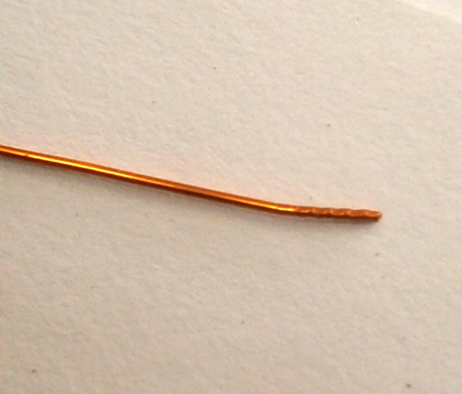
A few months ago, I acquired a Soviet era deck watch. Unfortunately,  the upper balance staff pivot was broken, but I was able to buy a new staff and, for a trifling NZ$100, a local watch maker replaced it for me (I have since acquired the courage to do this myself). He also offered to clean and oil it for another $2 -300, but I declined this, intending to do the work myself. When collecting it, I asked to see his workshop, where he and his apprentice son work and was interested to see that turning on his lathe depended on his skill with a graver. I gave silent thanks that I had been able to obtain a replacement staff, as to have it made from scratch would have been even more expensive.

After a week or two of running, during which I worked at ascertaining its long-term rate of going, it began to stop after about 20 hours, signifying that something was amiss, perhaps a piece of grit jamming a wheel at the low power end of the train or a problem with the driving force. At this point I suspected a problem with the spring or its barrel, but was later to wonder about the stop work. Overhauling the watch gave me an opportunity to illustrate some of its features.

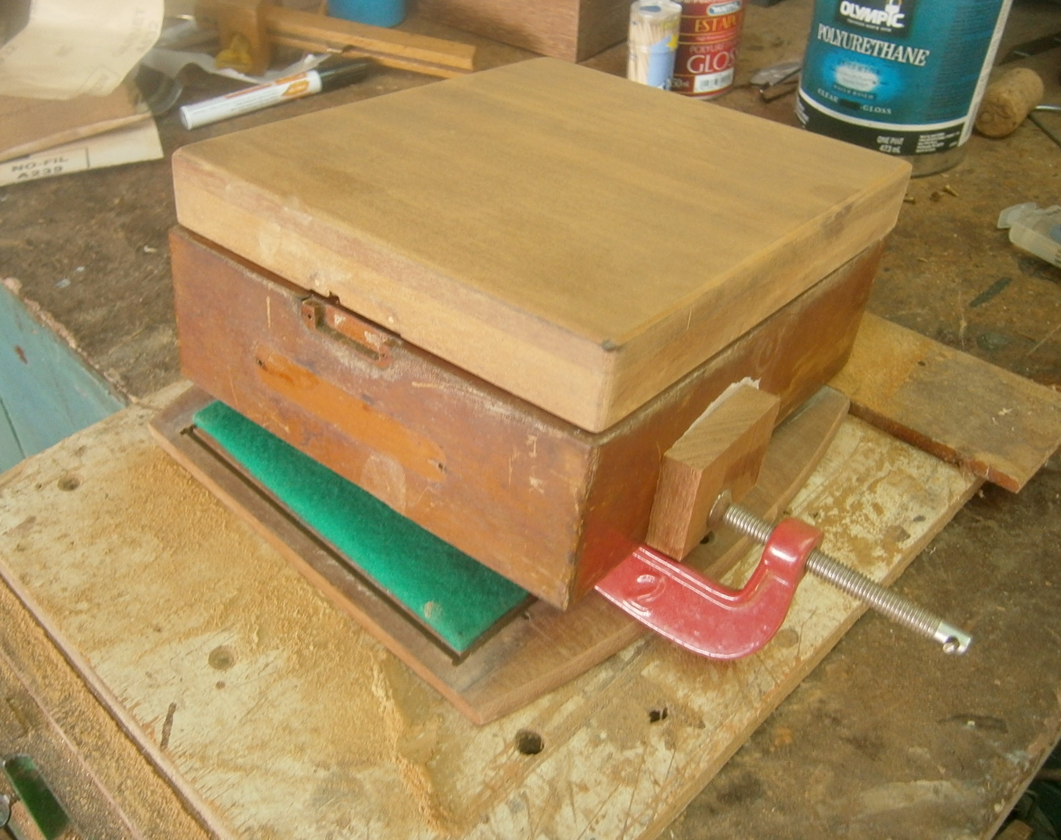
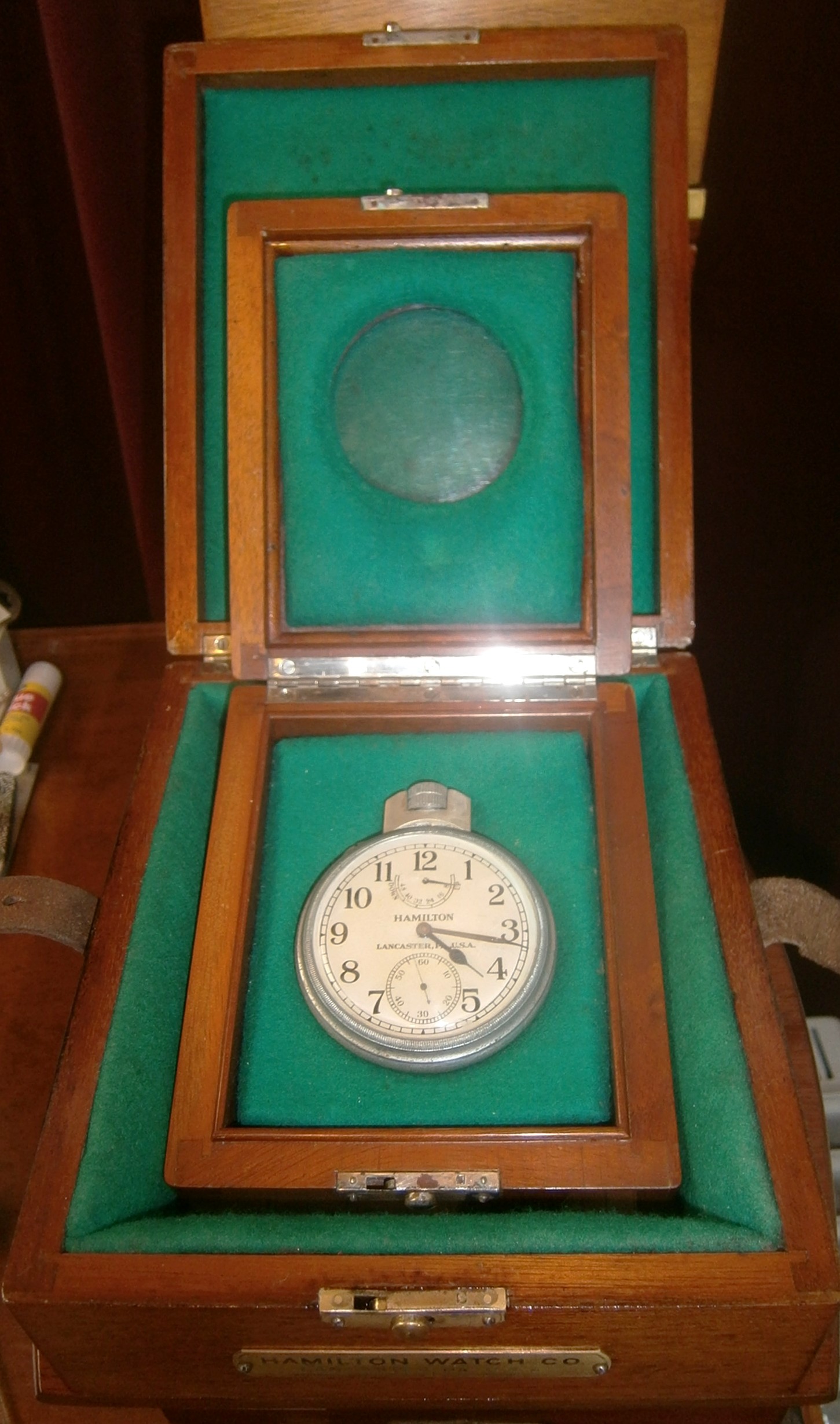
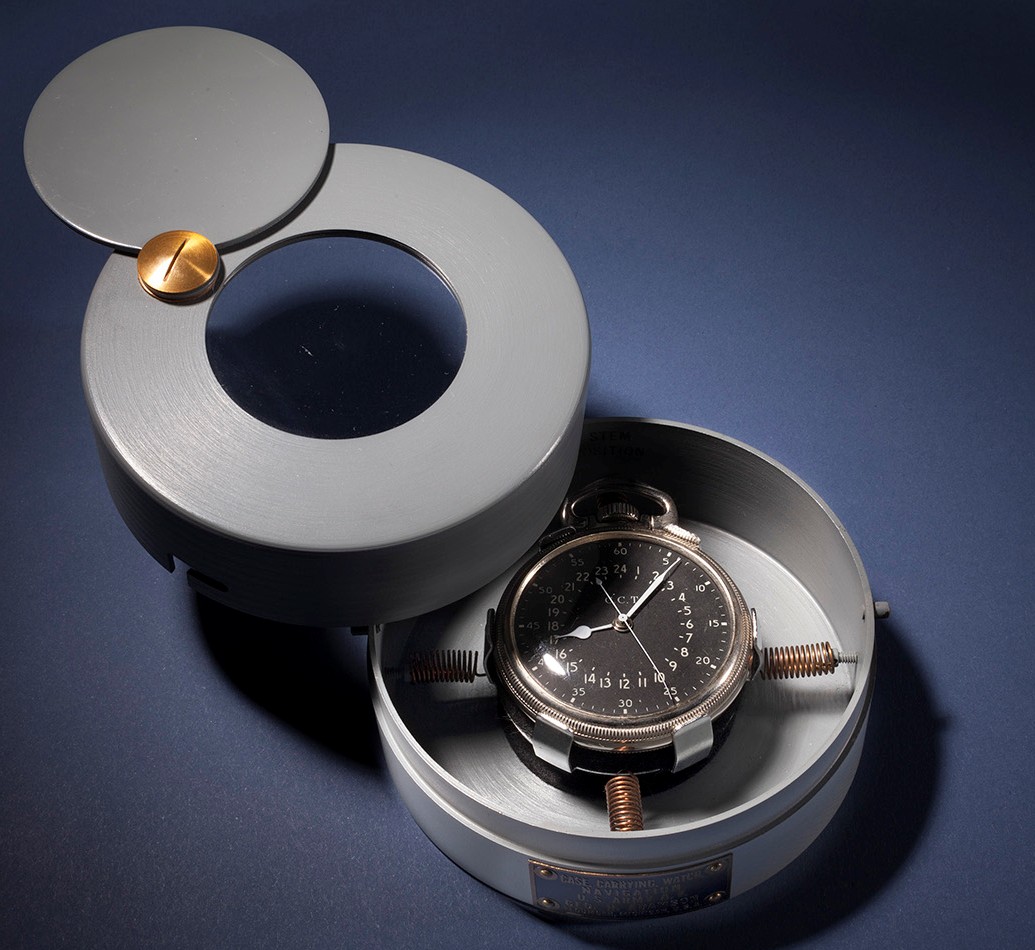
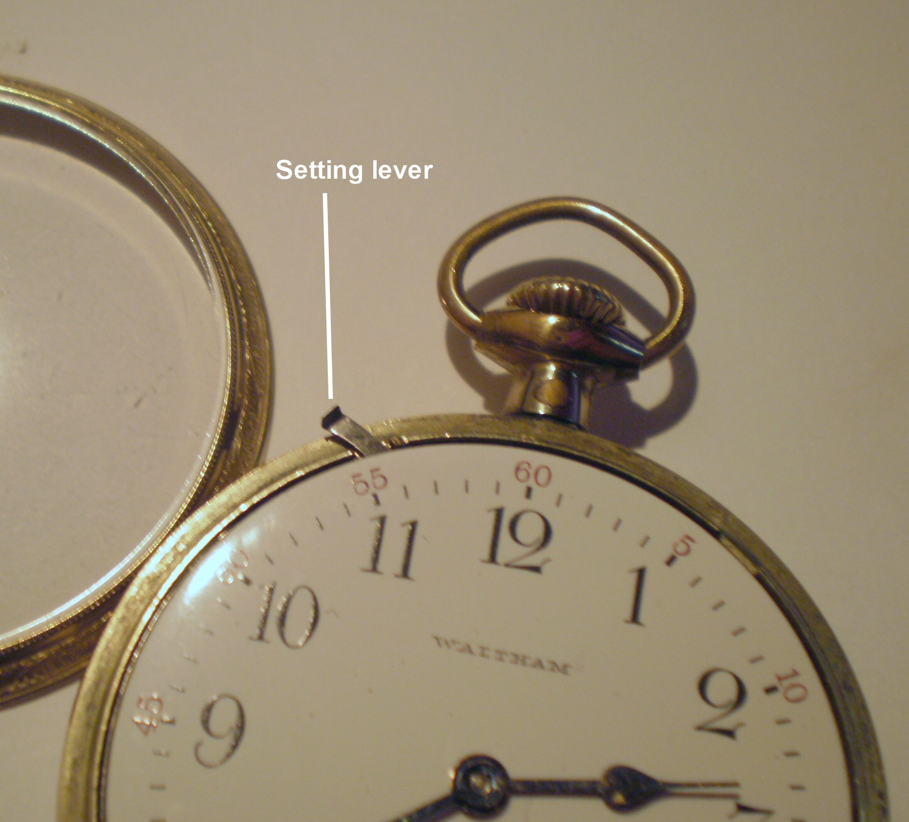
The watch looks like a large, open faced pocket watch with a centre second hand and is contained in a three part wooden outer case (Figure 1). While this particular version is stem wound and set, earlier versions were had a safety setting pin, and the space for this in the case is visible to the left of the stem.

Deck watch 001

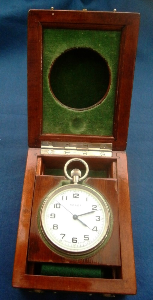
Figure 1: Deck watch in case.

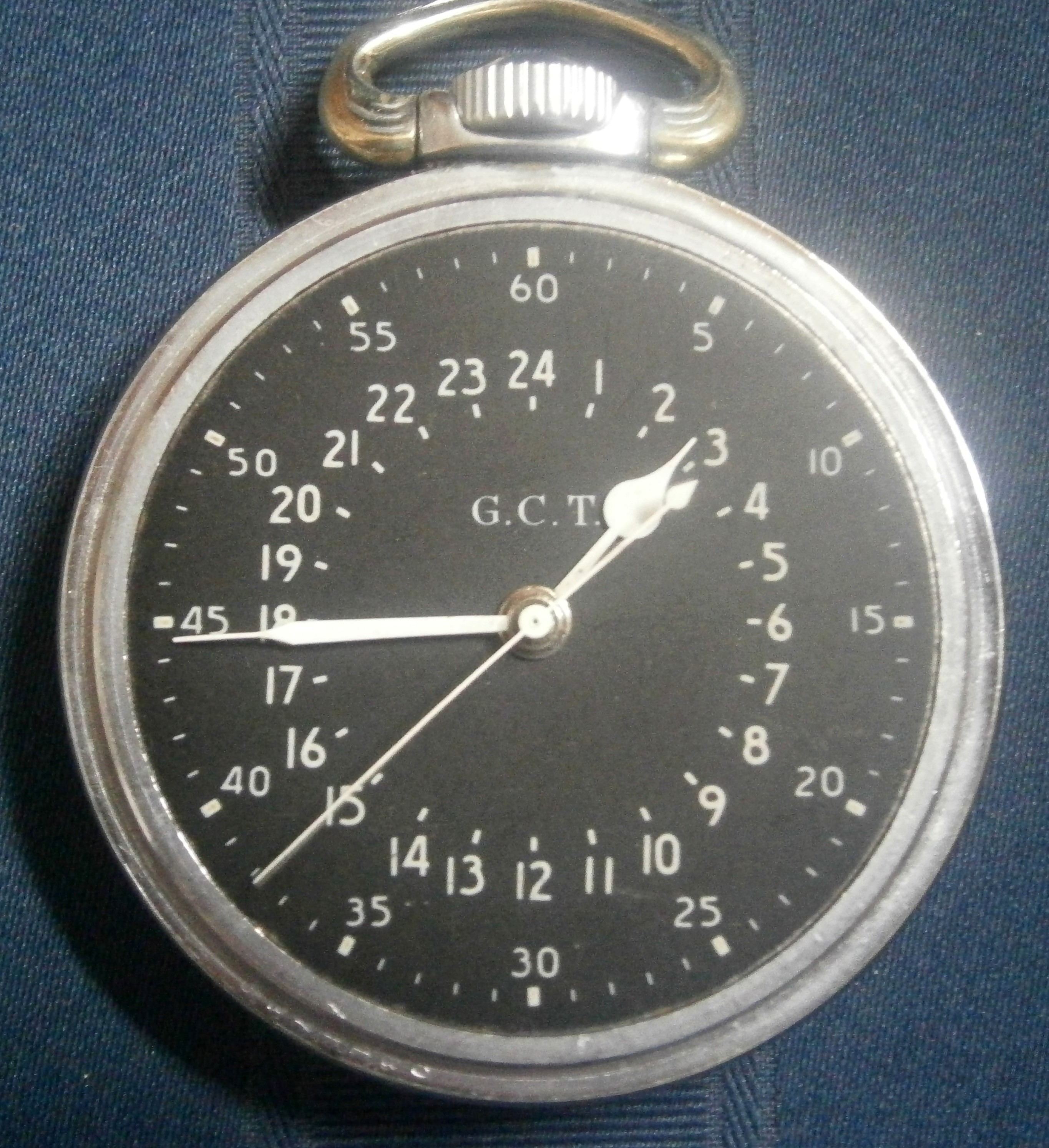
The watch is named “Polyet”  (“Flight”) while earlier versions bore the logo of the First Moscow watch factory. On each side of the 6 is found in Russian “Made in the USSR” (Figure 2). The face is protected by a heavy, flat glass and the bezel and watch case itself is made of chromium plated brass.

002 001

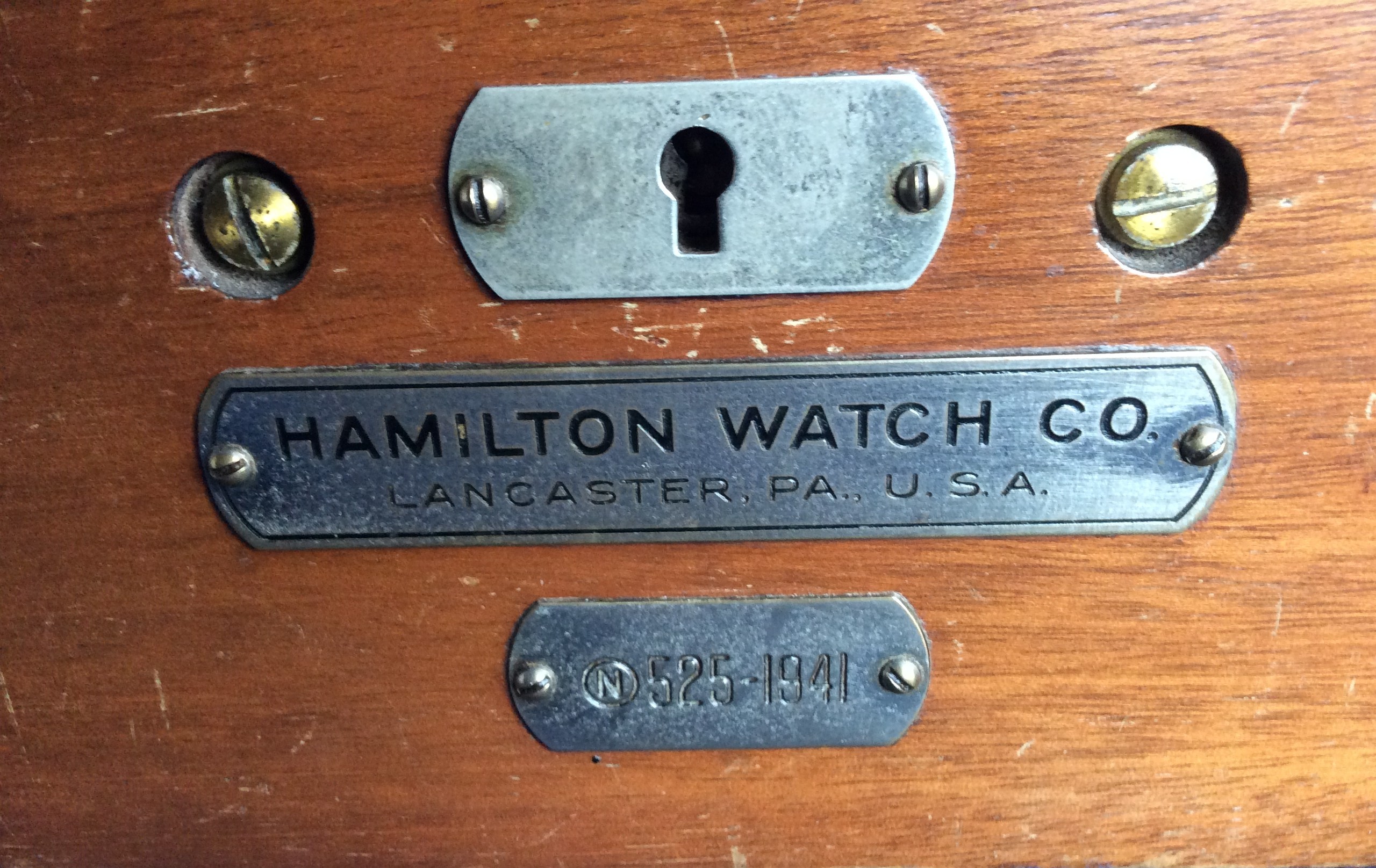
Figure 3 shows the placard on the front of the outer case. The first line reads in Russian “First Moscow Watch Factory,” and the second line “Named S M Kirov.” There is a certain irony here, as there is a strong suspicion that Stalin had Kirov murdered in Leningrad in 1934, because of his popularity, and following his death a tractor factory, a military medical academy and other institutions were named in his memory, including, as we have seen, a watch factory. The third line reads “Deck Watch”, while the last line reads GOST, an abbreviation for “State Standard” 17156-71. The outer case is very closely modelled on the outer case of deck watches made by Ulysse Nardin in the 1930s and 40s and, as we will see, so is the movement.

OLYMPUS DIGITAL CAMERA

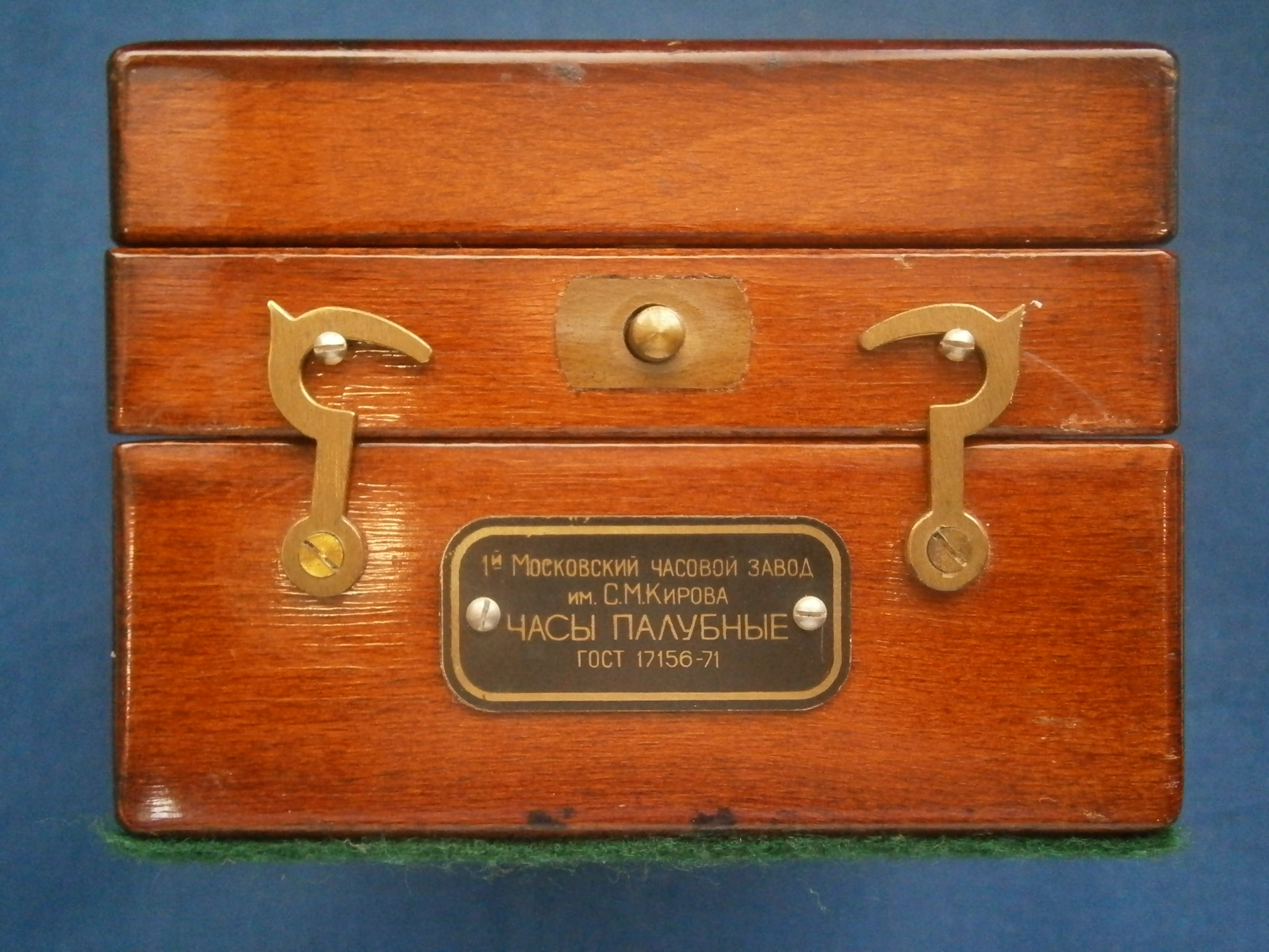
Figure 3: Front of outer case

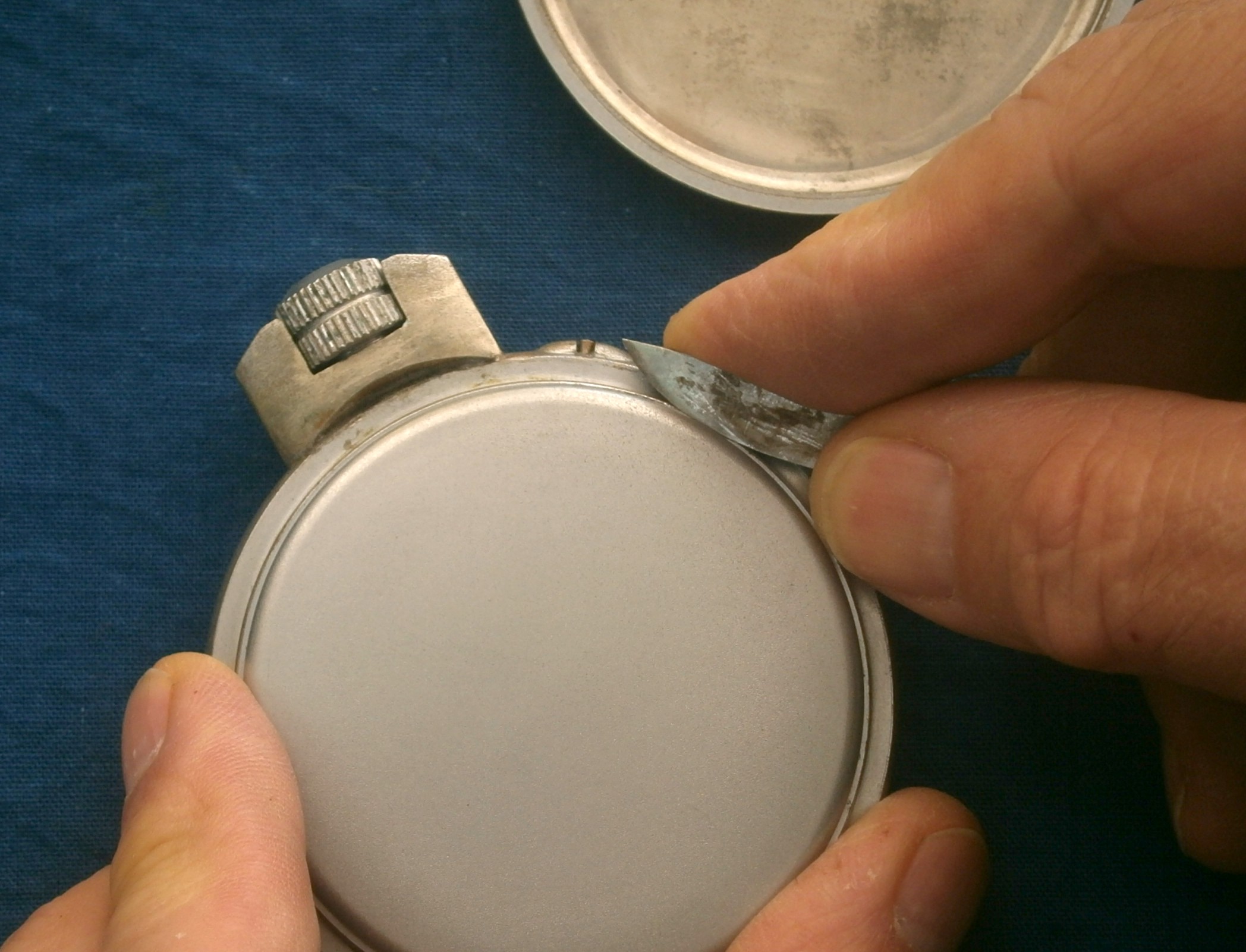
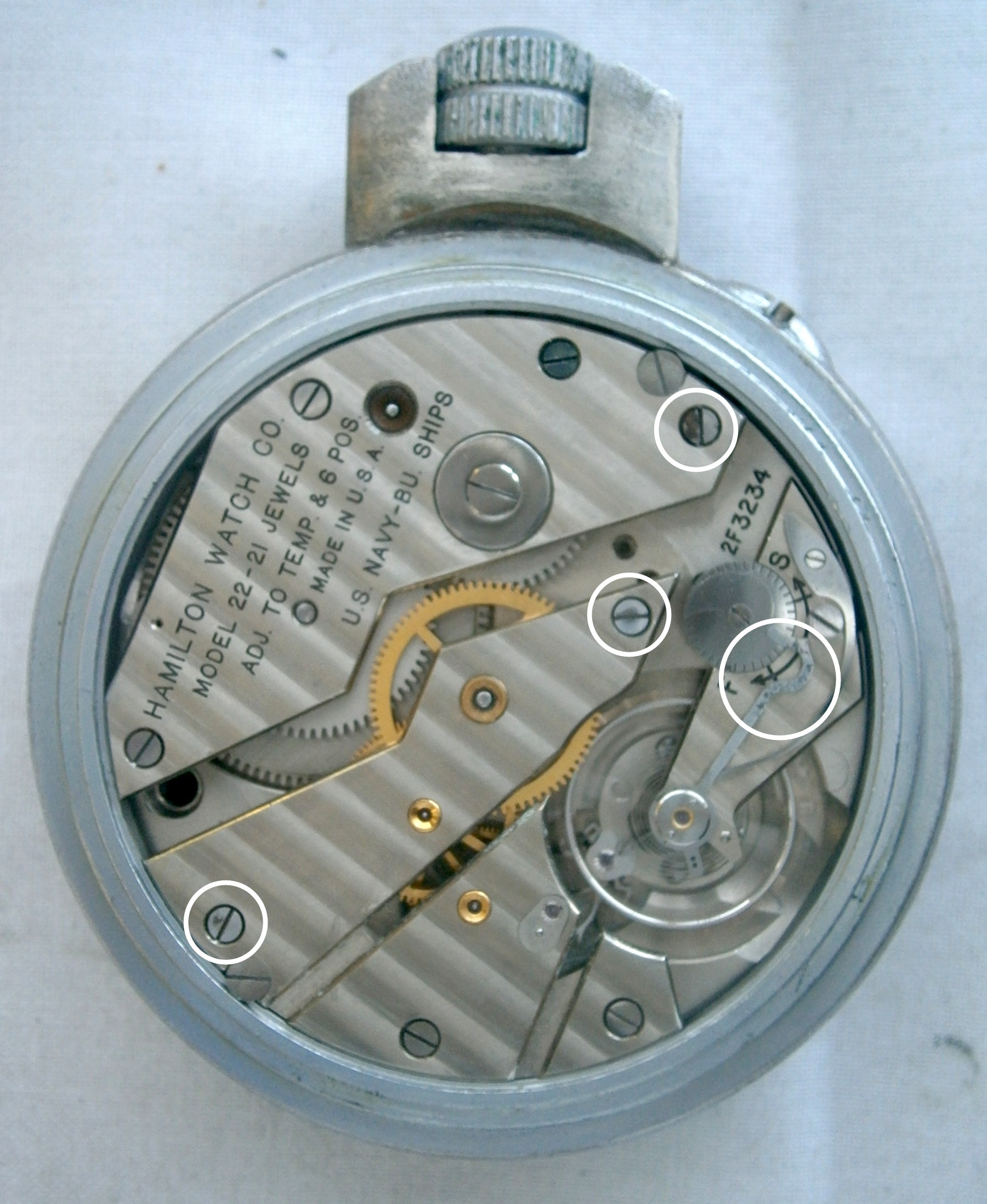
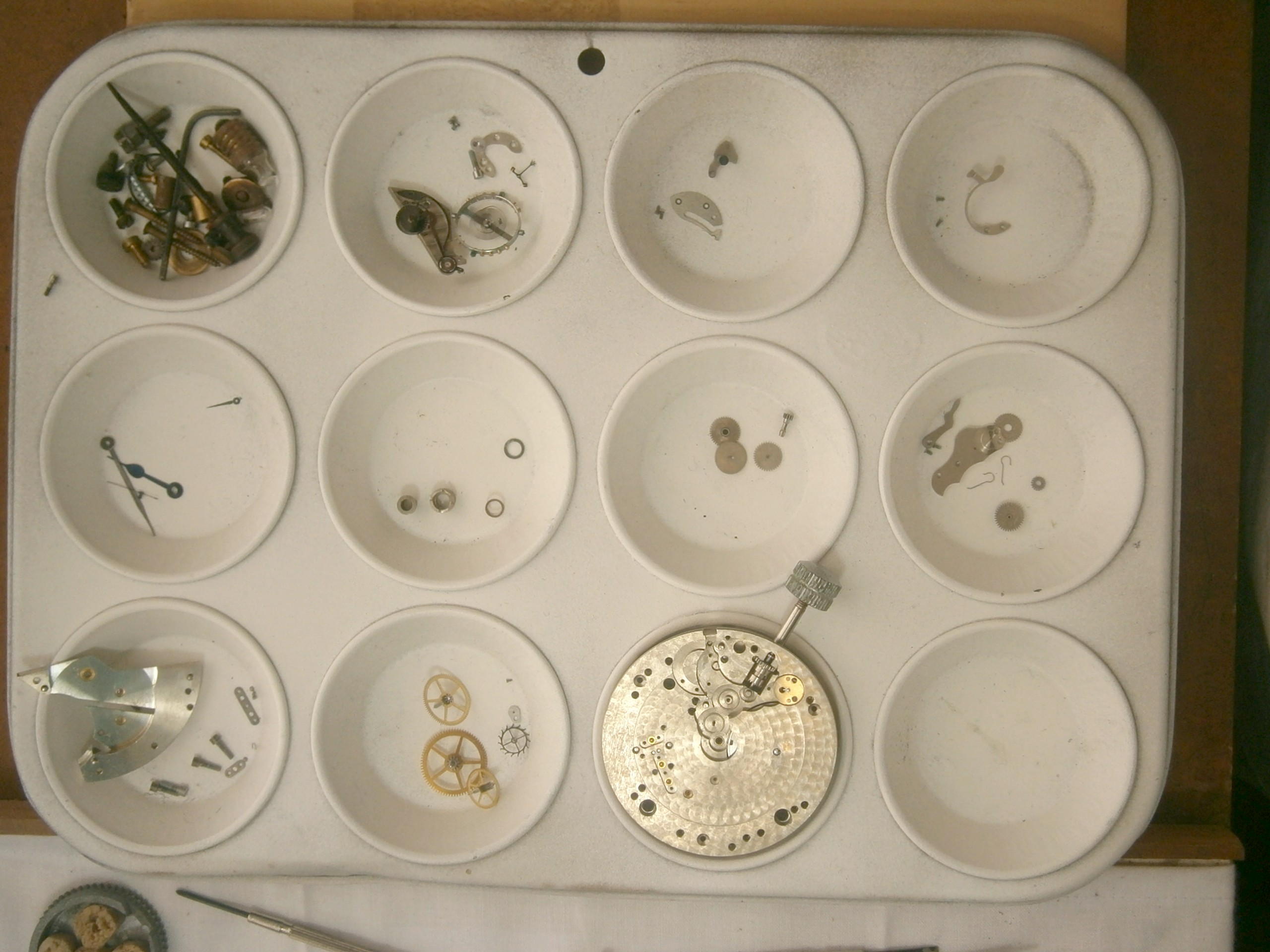
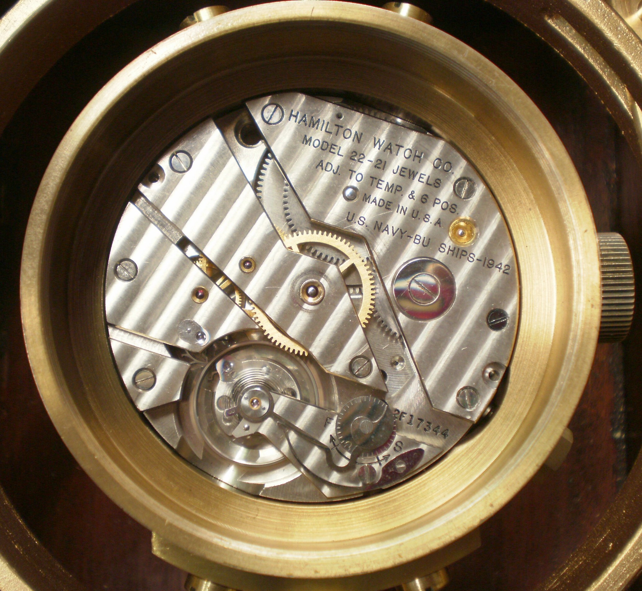
The movement is revealed by removing an outer snap off back and an inner dust cover and Figure 4 shows the movement with the major parts labelled. A Ulysse Nardin Deck watch from about 1940 is shown for comparison in Figure 5.  There is a close general similarity, the main differences being that in the Nardin watch the seconds hand, borne on the fourth wheel arbor, is at the more usual six o’clock position and there is a safety setting pin.

Parts labelled

Figure 4: The movement.


Nardin movement

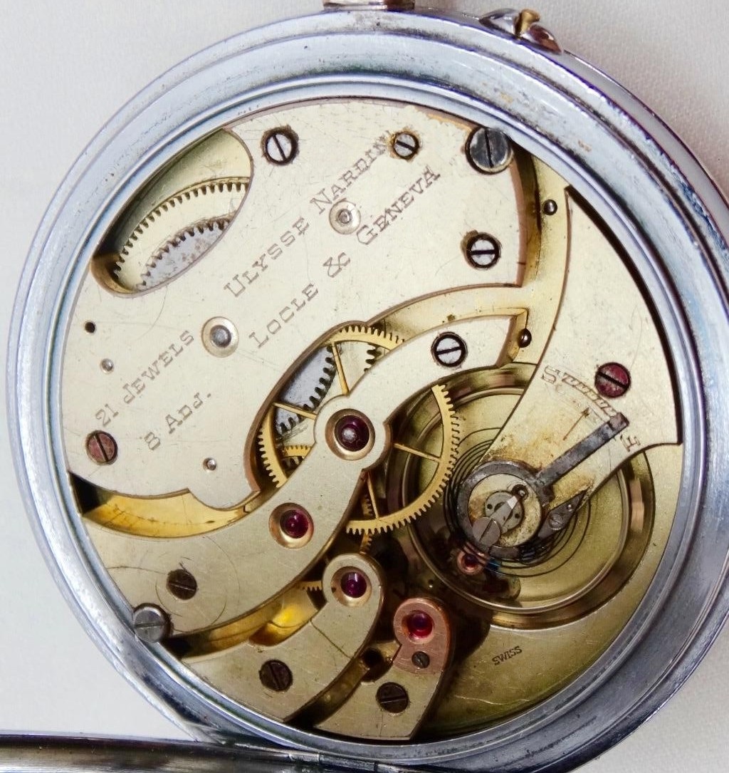
Figure 5: Movement of Nardin deck watch.

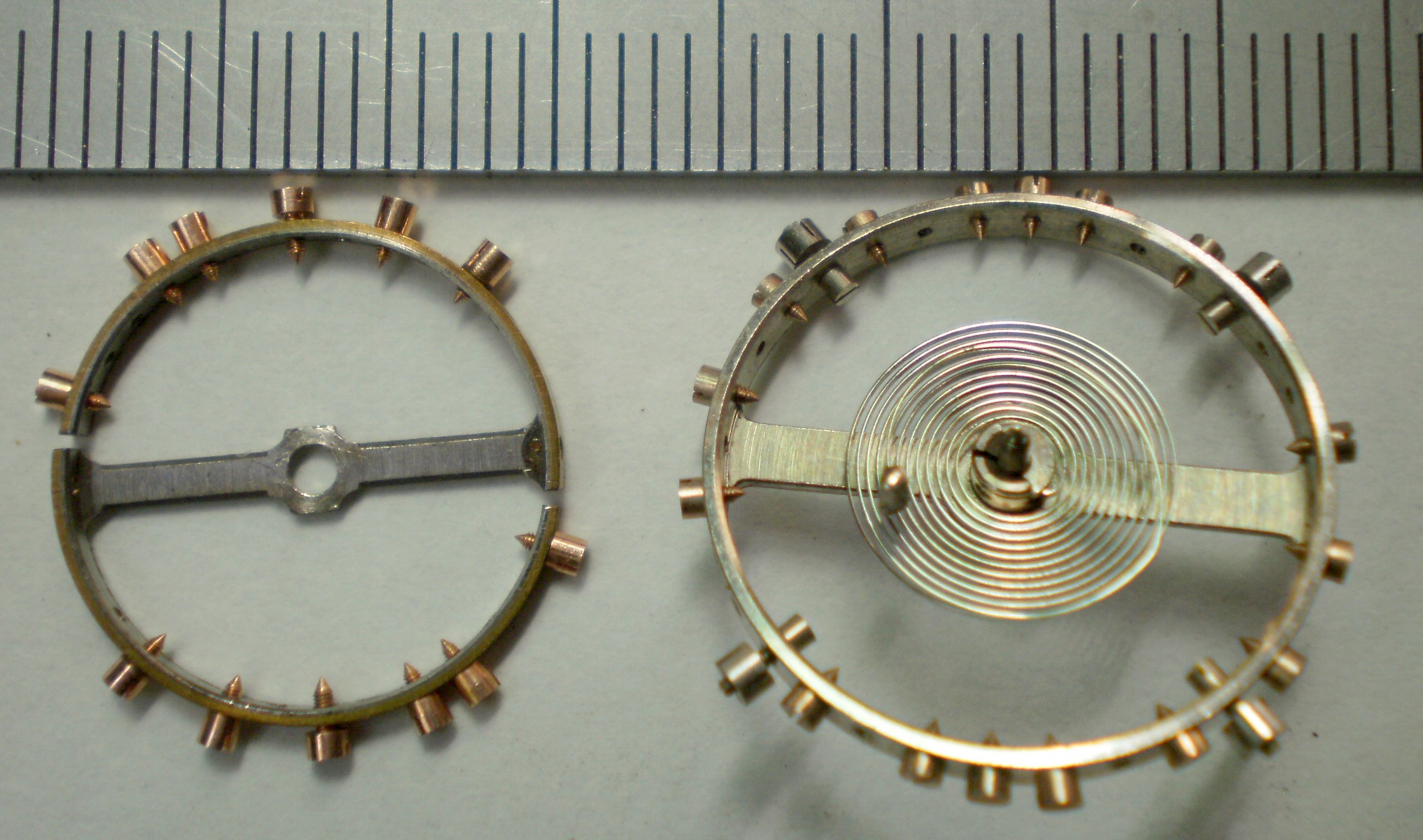
Both watches have more than the usual complement of jewels because the balance, the pallets and the escape wheels are all provided with end stones and the train is jewelled to the centre wheel. The extra jewel in the soviet watch is accounted for by the central seconds pinion pivot. The Polyet cocks, plates and wheels are gold plated, with the edges of the cocks carefully  bevelled, with a beautiful Geneva wave finish to the cocks. This latter has no function other than to demonstrate the high quality of the time piece, while remaining hidden from all except the watch maker or repairer.The “1-77” indicates that it was made in the first quarter of 1977. The split, bimetallic balance wheel and the lever escapement are conventional as is the train, except in the region of the seconds wheel. Figure 6 shows the area with the cock removed.

Seconds

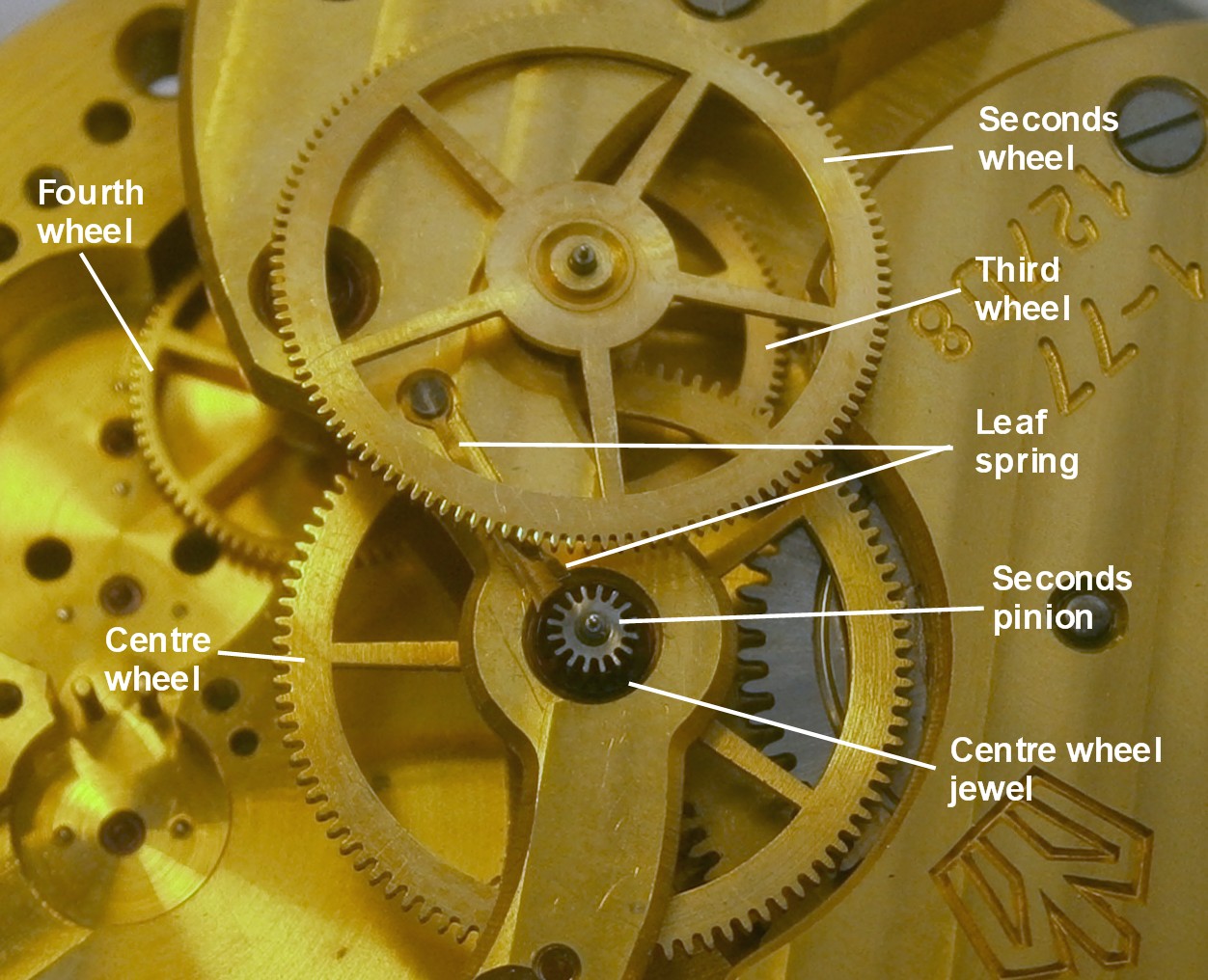
Figure 6: Seconds wheel and pinion.

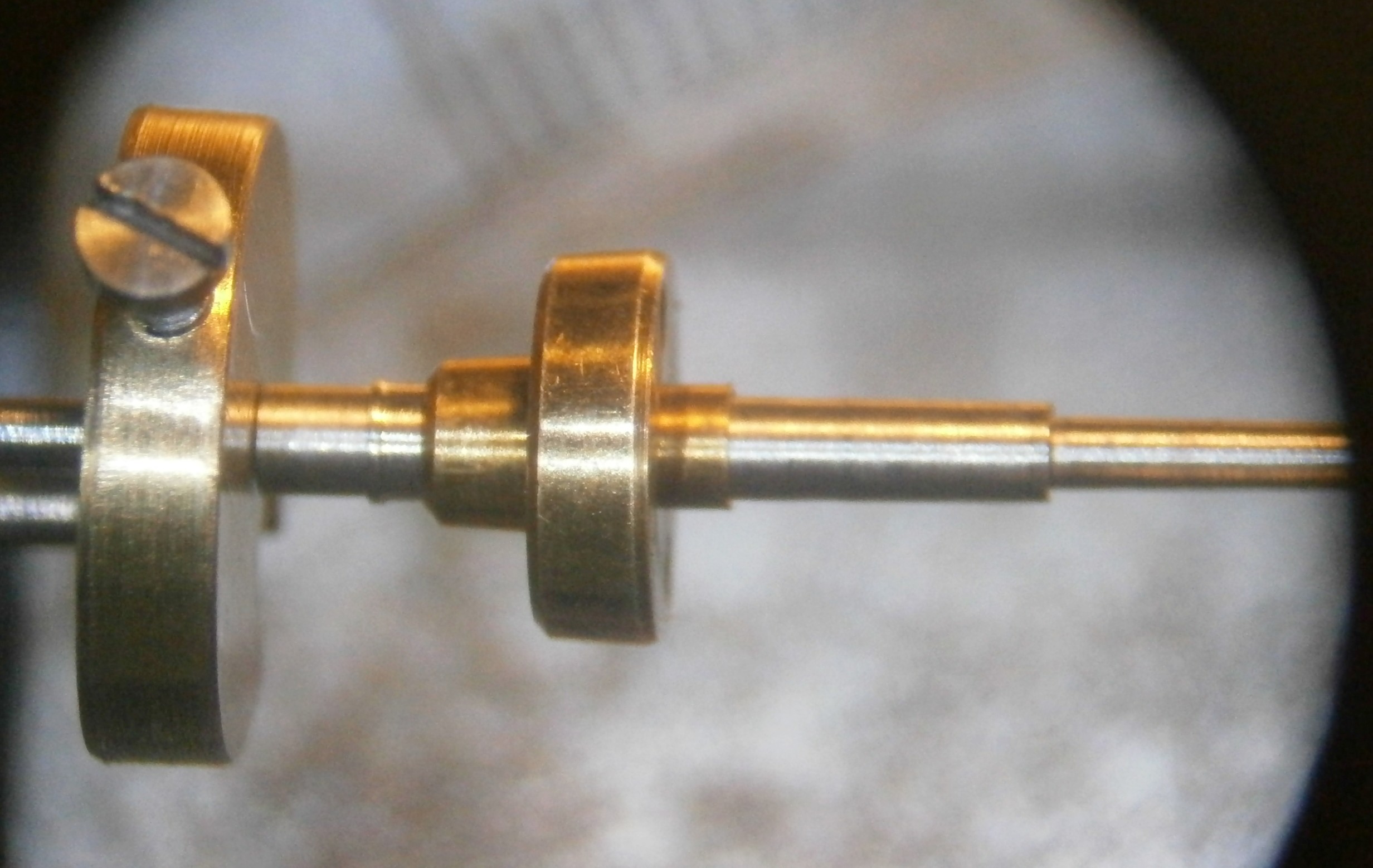
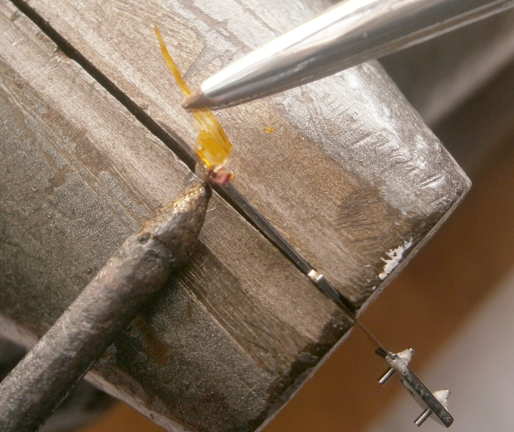
Some watches with centre seconds hands have the jewel for the third wheel pivot mounted in the upper train plate or cock, with a projection through the cock on which the seconds wheel is mounted with a press fit. In this watch, the cock is cut away and the jewel is mounted in a separate cock, which is also jewelled for the pivot of the seconds pinion. The latter is held in its jewel by a delicate little leaf spring which presses against the underside of the pinion. Assembling the cock for the seconds wheel and pinion is difficult to manage without the spring slipping from under the pinion and I found the easiest way was to back off the little screw that holds the spring, to assemble the cock, to manoeuvre the spring into its proper place and then to tighten the screw.

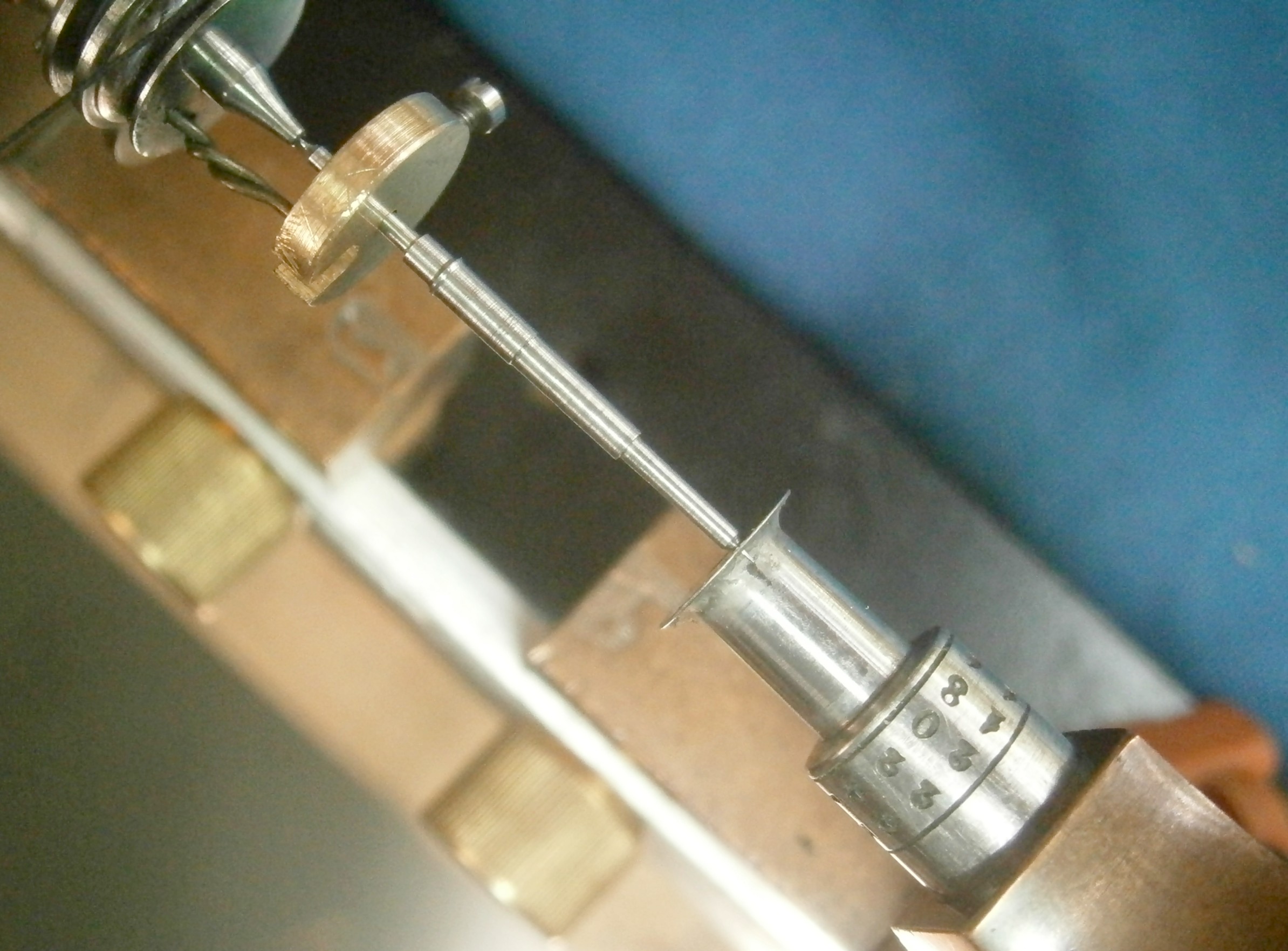
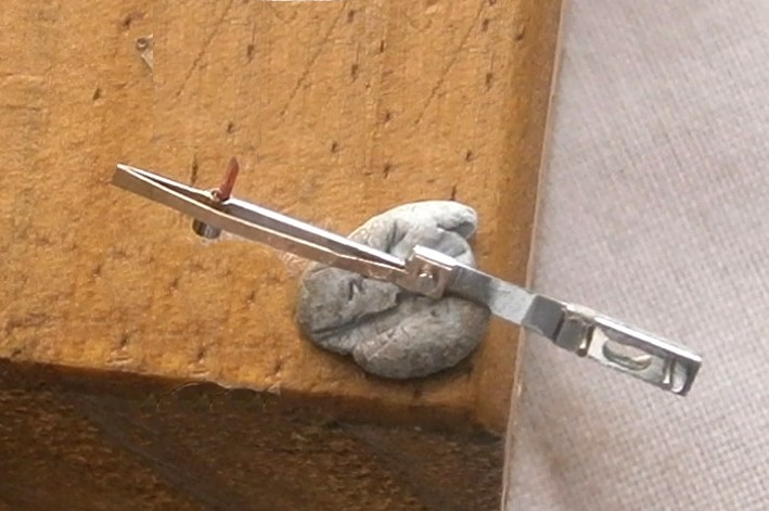
The winding and setting mechanism are conventional but the stop work for the winding is a little unusual for a relatively modern watch in that it uses a Geneva mechanism (Figure 7).

Geneva

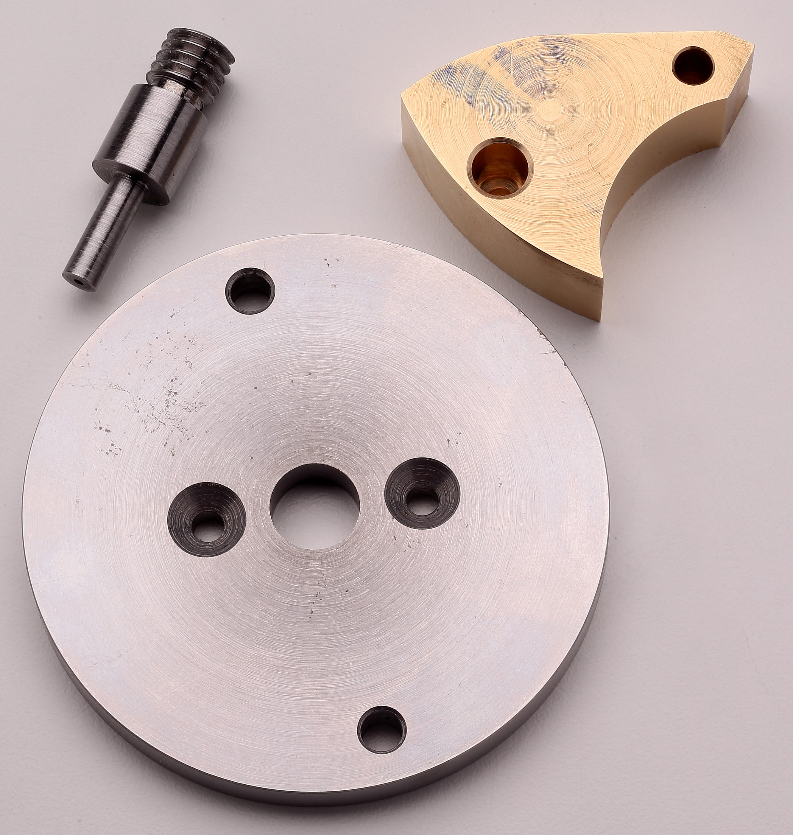
Figure 7: Geneva stop-work.

The mechanism is accommodated in a figure 8-shaped depression in the lid of the spring barrel. A square on the spring arbor carries a disc with a tongue and the disc is cut away a little each side of the tongue. Another disc having six arms is mounted and rotates about a shouldered screw. Five out of the six arms have concave ends, but the sixth has a convex end. As the spring is wound, the tongue causes the Geneva to rotate up to five times, with the concavity on the end of each arm allowing clearance for it to do so.However, when it reaches the sixth arm, there is no clearance and winding is brought to a halt.

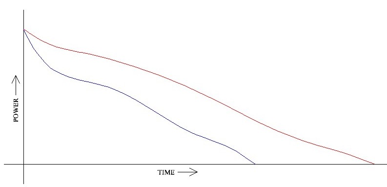
While it might be thought that the purpose of this stop work was to prevent “over winding”, most people with even a slight knowledge of watch and clock mechanisms will know that it is not possible to over wind, though it is of course possible by brute force to break parts of the winding mechanism. Rather, the purpose of the stop work is to prevent the last part of the spring in contact with the spring barrel from coming in to play, as its power is different from that of the rest of the spring and the power delivered to the escapement and balance wheel would vary too much for good time keeping, Of course, the balance spring is adjusted to be isochronous as far as possible, that is to say that its period of swing is the same whatever the amplitude of the spring, but nothing is perfect…

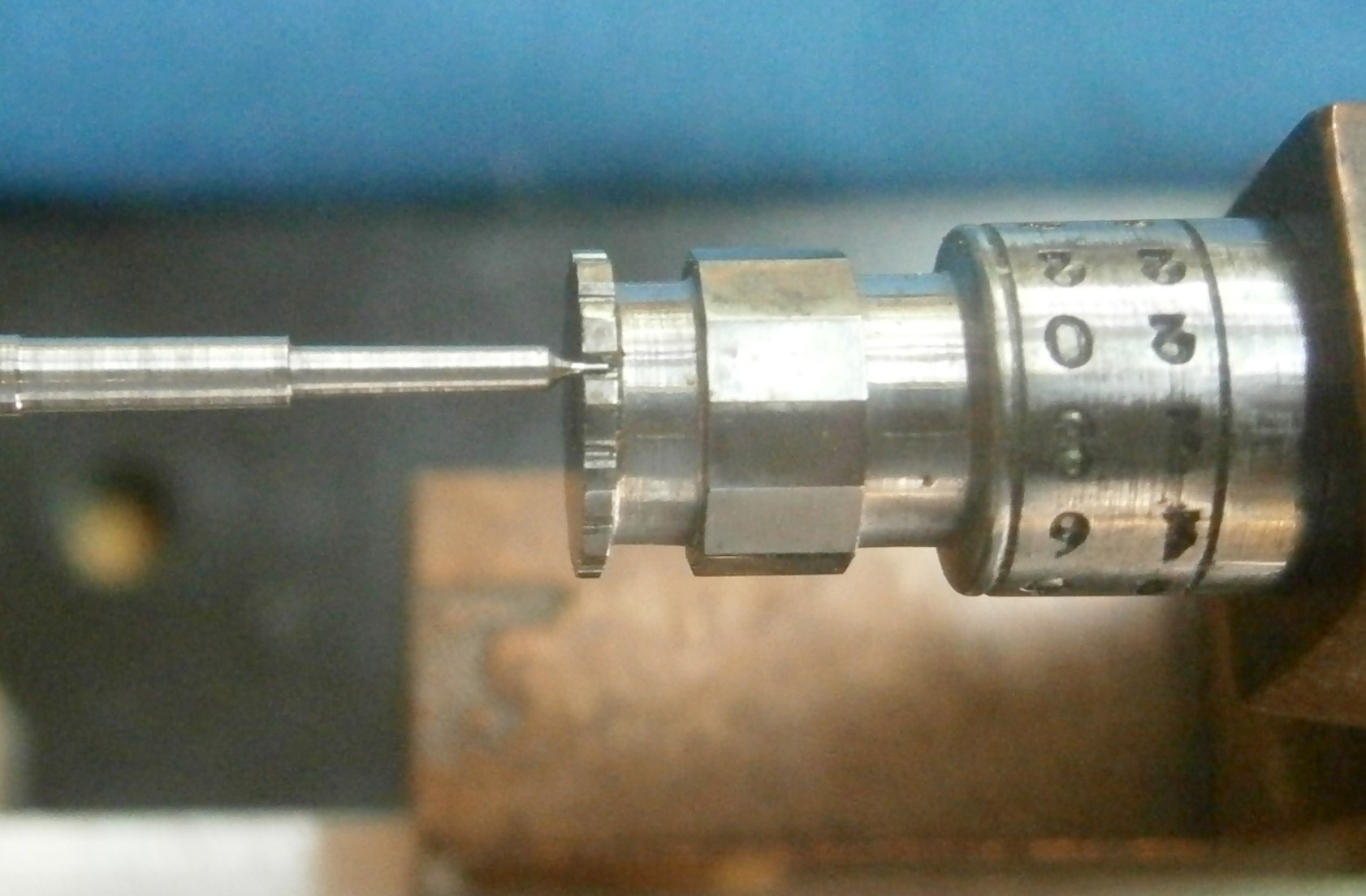
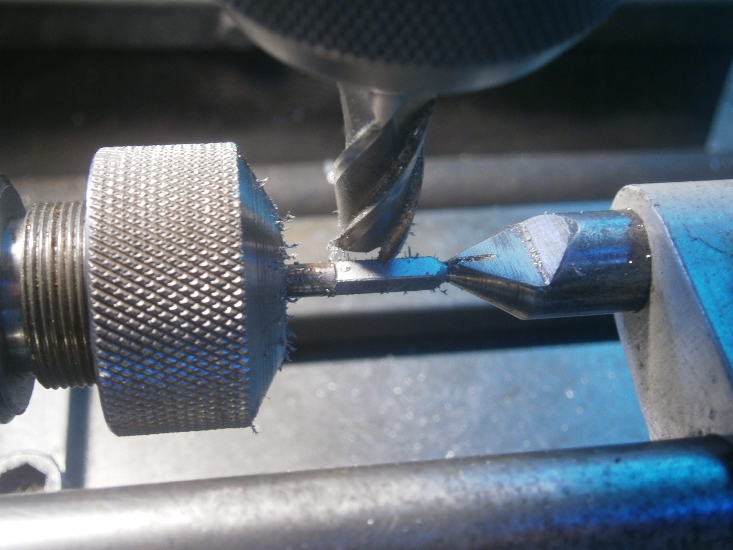
When I got to the spring barrel, I found that the square had partly disintegrated, perhaps because it had been left dead hard and cracked from a sharp corner or because of the application of brute force (not by me!). At any rate, I was obliged to graft in a new square, and after a thorough clean and oiling of the movement, it has since performed as it should.

I hope you have enjoyed reading about this brief exploration of a fine navigational time piece. If so, I am sure you will enjoy “The Mariner’s Chronometer”, obtainable through amazon.com and its associated world-wide branches.


19. Making an upper balance cock.

8 02 2016

Tim White, from down under in London, very kindly agreed to provide a “Guest Post” about his making a chronometer balance cock. I have added some notes in blue. He is in the process of copying a Hamilton M21 chronometer, using some of the original dimensioned drawings.  Most chronometer upper balance cocks are in the form of a Z (Figure 1). Traditionally, the folds were made by cutting a 92 degree groove in the metal almost the whole way through, bending to 90 degrees and running solder into the groove (See Post 8, Figure 7), but manufacturers later probably used extrusions that were then finished to size and contour.

Fig 3.12.jpg

Figure 1: Common form of balance cock (from The Mariner’s Chronometer).

However,  the chronometer example supplied to the Hamilton Watch Co. in about 1940, for them to assess, was by Ulysse Nardin (Figure 2), who milled it from a solid block and attached it near the edge of the upper plate, so Hamiltons did too (Figure 3). The Nardin method seems to be somewhat over-thought, needing many operations and several settings to complete.

s-l1600 (1)

Figure 2: Ulysse Nardin balance cock.

Internal curves

Figure 3: Underside of Hamilton Watch Co. balance cock

Tim began with a piece of 1½ inch (38 mm) square brass bar which he faced slightly over length in order to mark out and drill 6.5 mm for the 1/8 inch cock retaining screw and counter-boring for the screw head. The hole and counter-bore for the upper balance pivot and its jewel must be accurately located relative to this hole. All other dimensions are “air fits”, that is to say that they do not need as precise positioning and dimensioning, since they are not in contact with other parts. Note that the curves marked with green lines in Figure 3 are not necessary for the part to function and could have been omitted as an economy measure.

Tim continues:

Put in the small 4 jaw and face down to within .005” (0.13 mm),  removing to measure. Remove using 2 jaws only. Clean and replace.

Tighten lightly, then applying tailstock barrel and apply strongish pressure, re-tighten 2 jaws quite strongly. Remove barrel and face .001” at a time measuring after each cut and clean between cuts. Take three final cuts stopping the lathe between cuts. (A depth micrometer, measuring against the face of the chuck, is handy for getting the correct thickness without having to remove the workpiece from the chuck. I use a lump of copper to tap the first face into contact with the face of the chuck.)

Next, I coated one side of block with marking blue and traced the outline of the original cock. It’s difficult to draw the cock from the plans as they are not completely dimensioned, as well as having centres that lie outside the block. In order to cut the 3 curves I made 3 discs of the right diameters attached to a mandrel. Referring to Figure 4, which is modified from the original Hamilton drawing, for curve A, I mounted the block in the machine vice of the vertical slide in the lathe and then aligned the edge of the disk with the scribed outline of the outside diameter. I replaced the disc with a fly cutter with an adjustable cutter and adjusted the tip of the cutter using a calliper until it had the correct diameter. I then cut the curve.

Copy of BALANCE COCK P5labelled

Figure 4 : Outline curves (Hamilton Watch Co., modified)

Next I machined the straight part B, Fig 4.  I then machined the curve C , Fig. 4, mounting the block on the 3.4in (86.36 mm) disc so that the curve marking is exactly lined up with the edge of the disk placing it by carefully marking, drilling and tapping holes so that it can be screwed to the disk. NB I made a counter weight which was weighed and machined until it was the same weight as the block. I then screwed it to the other side of the disc opposite the block and machined it at around 600 rpm (Figure 5 ).

BALANCE COCK 2

Figure 5: Set up for machining curve C

To machine curve D, Fig. 4,  I used the Sherline rotary table. The block could not be rotated by the lathe because the flat straight AB would hit the cutter. I attached the table to the vertical slide with the operating handle protruding towards me. I used the 2.8 in. (71.12 mm) disc (2 x 1.4 in) centred on the table using the table centre arbor and a spacer to plug into the disk. I secured the disk to the table using two sockets in the T slots. I then secured the block to the disk holding it with a small clamp while aligning the curve with the edge of the disk. I then centre popped through the two holes in the block using hardened centres of the correct diameter (transfer punches). I then drilled and tapped the holes and screwed the block to the disk.  Using a 7mm high helix end mill I then machined the short curve manually using small cuts of around .003in (0.08 mm) watching to ensure the mill never got near the flat area. This worked very well. The finish on all surfaces was good enough so that I could sand with 400 wet/dry and finish with 2000 followed by a Simichrome polish.

To machine the inside cuts I attached a round steel plate to the rotary table. In the middle of the disk (bored .4375” – 11.11 mm) I inserted a threaded pin screwed into the table centre. It has a protrusion which is the same diameter as the jewel hole. It protrudes only about 0.075in (1.90 mm) and is used to locate the jewel hole end during machining (Figure 6).

Central pin

Figure 6: Locating pin for jewel hole, and face plate.

The other end is secured by an M3 screw secured into the disk. The table is attached to the vertical slide. The cock is centred using a pin, which has a reduced diameter end .188in (4.77 mm) diameter. Its OD is 3/8 in (9.53 mm) and is held in the headstock spindle using a 3/8in collet. The vertical slide and cross slides are adjusted until the end of the pin goes into the jewel hole. The cross and vertical slides are then locked. Machining is carried out with a milling cutter held in the lathe spindle and the cut is put on by advancing the lathe saddle. I used a dial indicator to monitor cutting depth. I started the cutting at the jewel hole end and progressed outwards. This method worked very well with the M3 screw and centre pin securing the work piece. Figure 7 shows the workpiece secured to the rotary table, ready to be mounted on the vertical slide of the lathe. Originally, the part would have been machined on a vertical milling machine.

Rotary table 001

Figure 7: Work piece mounted on rotary table.

The curve E, Figure 4, is formed by making a filing button set-up using an OD of .400in (10.16 mm) and an ID of .188in (4.77 mm) to fit the hole. These hardened buttons, one each side of the part, were classically called “cheaters”. When the part is to size and shape, the file skids of the buttons.  I ground off any excess then filed the remainder using fine small files. Then I used 2000 grade wet and dry and polished the work with Simichrome.

Figure 8 shows the part after machining, with Figure 9 showing the finished part alongside a Hamilton Watch Co, original. The latter was made of nickel silver, similar to 60-40 brass with about 20 percent of the zinc substituted by nickel, to give a hard, corrosion resistant, white metal. Holes remain to be drilled for securing the balance spring, the upper balance jewels, and the steady pins which ensure that the cock is correctly located on the top plate.

Finish machined

Figure 8: Part finish machined.

BALANCE COCK  4_1

Figure 9: Hamilton original (left) alongside polished new part.


18. Turning a Chronometer Balance Staff

1 02 2016

Turning the balance staff for a chronometer is very different from turning the same item for a watch. For a start, even for a large pocket watch, the staff is unlikely to exceed 8 or 10 mm in length, whereas my example is over 26 mm long, but not greatly thicker, so one has to be constantly aware that the work piece may flex under cutting loads. Since the late 1700’s, engineers’ lathes have been equipped with compound tool slide rests, a sort of “iron hand” to hold and guide the tool in a linear fashion, but for some reason, watchmakers, even today, often use the techniques of the wood turner, albeit on a greatly reduced scale, holding and guiding the cutting tool (“graver”) by hand. It may be that it was hard to justify the cost of a compound slide rest and most of the watchmaker’s lathes on the second hand market today do not have them. Those that do, attract much greater prices than those without.

I recently made slide rests for my Lorch watchmaker’s lathe since I do not have the years left to acquire the skills with the graver. In any case, I would no more think of using a hand tool at the small scale of the chronometer than I would for turning larger diameters on an engineer’s lathe. To put it another way, I proceeded as the amateur engineer of long-standing that I am, rather than as a craftsman watchmaker.

My first task was to take the dimensions of an intact staff and make a drawing. While having a staff with a broken pivot may seem to place one in difficulties, it is a fair assumption that the pivots on both ends will be the same. If both are broken off, one may have to cut and try in the chronometer for which the staff is destined. To measure the small diameters it is necessary to have a clean and well-adjusted micrometer and technique does matter.

Clean the faces of the anvil and spindle by trapping a piece of clean note paper between them and pulling it free. Then check for zero error. Old codgers in engineering shops used to be proud of their sense of “feel”, but I reckon that Mr Mitutoyo must know a thing or two about micrometers and his firm recommend use of the ratchet or friction device, so turn the spindle slowly until the faces meet and until there is one click. Make a note of any zero error or, better, adjust the barrel to read to zero. If you use exactly the same technique when measuring, the measurements will be consistent to within less than 0.005 mm. If you gaily twirl the spindle so the spindle face hits the anvil hard or you twirl so the ratchet sounds like a soccer rattle, they won’t be.

Measuring lengths is a bit more difficult than diameters, but on the whole, they are less important. A steel rule calibrated in half-millimetres and a hand lens may do. A hand lens equipped with a measuring reticule is better and will give measurements precise to 0.1 mm. Better still is a microscope with a moving stage. These usually have verniers that allow measurements to be made with ease to 0.1 mm. To measure over-all length a micrometer is best and the technique is to hold the instrument with the spindle vertical, to rest one end of the part on the centre of the anvil and, while slowly advancing the spindle, move the other end around, exploring the face of the spindle, as it were, for the moment of contact. When this happens, back off a little, centre both ends and take a final measurement using the ratchet for one gentle click. Figure 1 gives the measurements of a Soviet MX6 balance staff (all figures may be enlarged by clicking on them. Use the back arrow to return to the text). If you already have a bench micrometer able to measure over 25 mm, (Post no.5, Figure 3) you probably will need none of this advice.

Balance staff MX6

Figure 1.

Sharp-eyed (or obsessional) readers will note that the reference length dimension does not equal the sum of all the sub-dimensions. This is because the sub-lengths were measured using a microscope moving stage, while the over all dimension was measured using a micrometer, precise to 0.01 mm. Note too that the seats for the rollers, the balance collet and the spring collet are all tapered. It is difficult to be exact about the amount of taper, as the differences in diameter between the ends of the tapers are so small, but the included angle seems to be around 0.8 to 0.9 degrees.

Pivot wire comes in various sizes, including a nominal 2 mm, which in my samples are 1.96 mm in diameter. It comes ready hardened and tempered to a dark blue colour, which is quite a lot harder than mild steel and which can be made much harder, glass hard if need be, but this is too brittle for our purposes. Since all the tapers on this staff are pretty well the same, the first task is to set over the top slide to turn a taper of 0.85 degrees. There is no hope of doing this by measurement and it must be done by cutting and trying on a piece of scrap material, adjusting the set-over until the difference in diameter at the beginning and end of a 10 mm length is 2(10 x tan 0.43) = 0.15 mm. While you are at it, check that the cutting edge of the tool is bang on centre height and that the tool is really sharp, by taking a facing cut on the piece of scrap and watching to see that there is neither a pip left behind (tool too low) or a pip is bumped off (tool too high). I have a large supply of discarded tungsten carbide engraving cutters that I convert to lathe tools for small work and they can be brought to razor sharpness with a fine diamond lap.

Once these adjustments have been made, turning can begin by cutting off a piece of pivot wire about a millimetre too long and holding it a collet chuck (or simply, collet) prior to facing both ends and measuring the length (Figure 2).

0 Face end

Figure 2: Facing the blank

If it is under-size, you will have to start again with another piece. Otherwise, using the graduation on the top slide thimble as a guide, reduce it to the desired length.

The next step is to turn a pivot on one end. The watchmaker of old would have blended the pivot diameter with the rest of the staff diameter by manipulating a graver to give a graceful curve. I use a tool ground flat on top (i.e. no top rake) and to the form desired on the periphery (Figure 3). Measuring the diameter of the pivot needs some care as there is only half a millimetre or so before the diameter starts to increase. I wear a pair of magnifying spectacles to make sure that only the parallel part of the pivot is being measured by the micrometer, and reduce it to 0.01 to 0.02 mm oversize to allow for loss in the burnishing.

2 Pivot turning

Figure 3: Forming a pivot.

The next part might as well be turning for the discharging roller, by allowing just enough of the work piece to project from the collet chuck. If you have enough magnification you may be able to detect a slight wobble of the end of the pivot at this point. This seems to be because the pivot wire is not perfectly round, combined with tiny errors in the collet. For this reason, I rough turn the part to about 0.1 mm oversize and complete the turning between centres (see below). Figure 4 shows this rough turning completed, with enough of the blank protruding to allow the seat for the impulse roller to be rough turned.

4 Rough discharge

Figure 4: Rough turning the seat for the discharging roller.

Next, the workpiece is reversed in the chuck to turn the other pivot and rough turn the seat for the spring collet. Figure 5 shows the staff with all rough turning completed. An idea of the scale may be had from the 3 mm diameter screw head visible in the bottom left corner.

5 Finished rough turn

Figure 5: Rough turning completed.

Figure 6 shows the set up for turning between centres. This ensures that all diameters are concentric with a line joining the two pivots, and also allows the part to be removed for measurement and put back between centres with an assurance that everything will still be concentric.  A brief explanation, referring to Figure 6, may help the non-turner.

Copy of 6 Finishturn collet

Figure 6: Turning between centres for collet seat.

Beginners may have wondered why the pivots take the form that they do, with an elegant curve rather than just being squared off. This is because the hole through the female centre has an outer, conical portion and an inner parallel portion whose diameter is larger than the diameter of the pivot, so that turning forces are taken on a larger and stouter diameter than the pivot itself (Figure 7). The latter, being only 0.2 mm in diameter would likely break off at the first cut.

Centre

Figure 7: Diagram of piviot (left) in lathe female centre (right)

The live centre rotates with the spindle of the lathe as does the driver, which engages in a slot cut into the side of the dog, a little disc of brass secured to the work piece by a screw. The dead centre remains stationary and must be lubricated. Thus, firmly held between centres, the work piece rotates with the lathe spindle and as the tool is traversed by the top slide it takes a cut. Further cuts may be made in a controlled way by advancing the cross slide with its calibrated screw. The top slide also has a calibrated screw, so that the length as well as the depth of cut may be controlled. In Figure 6, the balance collet is literally hanging about, so its fit may be tried after each cut.

Since the staff is very long relative to its diameters and slender, cuts taken must be very light as otherwise the cutting force will deflect the staff away from the cutting edge of the tool, or even spring the staff out of the centres, with consequent damage to the pivots. The tapers are very slow, so that even a small cut will allow a part to slide a considerable way (relatively speaking) on to the taper. Figure 8 shows the balance collet on its seat. A small tap with a punch will slide it up to the shoulder and seat it firmly on to the staff.

7 Balance collet fit

Figure 8: Balance collet on its taper.

The taper for the spring is dealt with next and after that, the dog is placed on the other end, the staff turned end for end, and the remaining two tapers finished to size. All is not lost nowadays if the seat is made slightly too small as an industrial adhesive such as Loctite 603 may be used to provide a permanent join, provided the gap to be filled is not too large. This cannot apply to the discharge roller of course, as it has to be adjustable, and should not be needed for the spring collet as the tolerance is large.

Now the pivots need to be polished and tradionally this was done using a Jacot tool, though the work can be done in a lathe fitted with a suitable tailstock attachment. All my technical dictionaries are silent on who devised this tool, but it was probably Henri Jacot, (1796 to 1868) who worked in Paris in rue Montmorency from 1833 with his brother Julien. On his death, the business was taken over by his nephew Albert Jacot.

8 Jacot g a

Figure 9: General arrangement of a Jacot tool.

The set up is similar to that used for turning between centres, as shown in Figure 9, except that there is no tail centre. Instead one pivot rests in a groove of such a depth that part of the pivot projects above the walls of the groove (Figure 10), while the other pivot rests in a dead centre, about which the driver rotates. Again, the curved part of the pivot plays a part in locating the staff in the device. The correct depth of groove for a given pivot is stamped in hundreths of a millimetre on the end of the tool. In Figure 10 it is 20/100 mm or o.2 mm

9 Jacot close up

Figure 10: Close up of Jacot tool.

Note that most Jacot tools for sale are not large enough to accept a chronometer balance staff, so in mine I carefully milled a register parallel to the axis of the device in two planes. After cutting it into two pieces I could mount it adjustably on a bar to maintain alignment.

As the staff is rotated towards the operator, a burnisher that rests on top of the pivot is pushed away, smoothing and polishing the metal as well as keeping it in place in its groove (Figure 11). It is commonly stated that the process work-hardens the surface, but I doubt that the pressures attainable are sufficient for this. Polishing also reduces the diameter of the pivot slightly. The burnisher is a piece of dead hard steel in which very shallow transverse grooves have been made by dragging it across a piece of emery paper.

10 Burnisher use

Figure 10: Burnisher in use.

The ends of the pivot are dealt with using a slightly different tool in the tail stock (Figure 11). Instead of grooves, the tool has a thin disc of steel with holes of various diameters to suit the pivot, so that as the staff is rotated, a burnisher can approach the end, to be manipulated in such a way as to slightly round the end. If this is overdone, a burr may be raised and if this happens, it can be simply removed by burnishing a slight chamfer.

11 Burnish end

Figure 11: Jacot tool set up to burnish end of pivot.

Figure 12 shows the finished staff, together with the parts to be mounted on it (the spring is slightly distressed and will need more work on it). It is important not to hammer the rollers into place as this risks splitting them, especially the tiny discharge roller which will probably need adjustment anyway, once it has been tried in the chronometer. If a roller will not slide far enough along its taper by pushing it it into place, it is a simple matter to replace the staff between centres on the lathe and remove a whisker or two with a burnisher or very fine file or oil stone.

13 Parts

Figure 12: Finished staff with parts to be mounted on it.

I hope my attempts will help to illustrate one way how to make a balance staff and that too many experts will not be aghast at my methods. I am always happy to receive kindly worded comments, suggestions and corrections.


17: Replacing an impulse jewel

30 01 2016

Escapement jewels may need to be replaced for a variety of reasons. An inexperienced repairer may try to adjust the position of the detent without first blocking the movement and, as an extra precaution, letting down the main and maintaining power. The result is sometimes that the movement “runs away” and jewels get smashed when the detent is released in a panic, instead of quickly getting a finger on to the fourth wheel. Sometimes a sharp mechanical shock will loosen the jewel, for example, when removing the roller from the balance staff; the jewel is secured in its seat with shellac, which is brittle. Injudicious use of alcohol to clean the parts will soften the shellac, which is soluble in alcohol. Sometimes the jewel will just work loose with handling, as happened to me recently when making a trial fitting to a new balance staff I had made.

Replacement is easy, provided one has steady hands and plenty of vision. A loupe may be enough for some people, but I prefer to use a stereo microscope with X 10 magnification, as the working distance is greater and it is easier to get plenty of light where it is needed. Simple ones are quite cheap on the second-hand market. One will also need a low wattage electric soldering iron and a few flakes of shellac, which may be obtained from specialty decorating stores, or possibly from your friendly local French polisher.

First heat up the iron (the business end is copper!) and with a cotton rag wipe off as much residual solder as you can from the tip of the iron. Then anchor the roller with the tip of the iron. Quite soon, you will see residual shellac start to melt, at which point with a pair of fine tweezers feed in a flake of shellac into the jewel seat. A steady pair of hands and two pairs of tweezers are then needed to set the jewel on its end with the acting face aligned with the radial side of the seat (Figure 1). It useful  to pose the parts on a sheet of thin glass, like a microscope slide. This helps to align them correctly and prevents and plastic on the stage of the microscope from melting.

Impulse jewel 001

Figure 1.

The iron is brought into action again until the shellac melts and begins to run, when, with luck, the jewel can be slid into its seat and the shellac allowed to cool. As Figure 2 shows, the business end of a jewel which is simply being put back into its rightful place should be of the correct size , with its working edge concentric with the circumference of the roller. A replacement jewel may be too long, in which case its height will need to be reduced by rubbing the base on a diamond lap. If too short, it simply has to be manoeuvred into the correct place after softening the shellac with the soldering iron.

Impulse jewel 003

Figure 2

The final step is to check that the working face of the jewel has no specks of shellac or dirt on it. Excess shellac can be chipped away with, say, the point of a hypodermic needle and a brief wipe with a rag moistened in alcohol will remove loose chips from the roller.


16: A Ship-wrecked M22 Chronometer Watch Restored.

22 08 2015

All photos except the first may be enlarged by clicking on them. Return to the text by using the back arrow. Some of the techniques I have used to restore this watch may shock, but desperate problems sometimes need desperate solutions…

At a local auction, I recently acquired an M22 chronometer watch (see Post 11) in a wooden case and an outer transporting case. The son of the former owner told me that it had been used on board a 44 ft Alden ketch in the 1950s and later aboard a 43 ft yawl which his father had designed, built and sailed in the Auckland to Suva yacht race. This was probably in 1971, as there is a rating card for May of that year in the case. Shortly after the race, the yacht ran upon a reef and foundered, but was subsequently re-floated and, after repairs in Suva, sailed back to New Zealand. Figure 1 shows a photograph of the watch prior to sale as I forgot to take my own photo, so impatient was I to get started on restoring the timepiece..

Figure 1: Watch prior to sale.

Figure 1: Watch prior to sale.

Even at this small scale, it is possible to see the verdigris encrusted around the winding crown and its guard, while the transporting case, shown in the process of restoration in Figure 2, was scarcely in a better condition.

Figure 2: Repair of transport case

Figure 2: Repair of transport case

The base had warped and partly torn away from the sides, and in doing so, one of the nails had partly detached a large flake of wood from the side of the case. After completely detaching the the sides from the base and introducing glue underneath the flake with a flexible blade, I was able to clamp the flake back in place under a wood block with loss of only a small chip from one edge. It is possible to see that I have interposed a slip of baking paper between the block and the case, to prevent any surplus glue from sticking to the block. As all the varnish had perished, I started to remove the varnish from the lid while the glue was drying, with the result shown in Figure 2. When everything had been glued and clamped together, I cleaned up the verdigris-coated hardware, re-waxed the leather strap, gave the woodwork several coats of polyurethane varnish and re-assembled the case, with the pleasing results shown in Figure 3. The latch on the catch no longer worked and I laboriously filed up a new latch from 3 mm brass, with a slight modification to ensure that the tail of the latch remained in its guide at all positions. Happily, the inner wooden case was in good condition except for the perspex window, which was completely opaque and so brittle that it crumbled almost to the touch. I replaced it.

Figure 3: Restored transporting case.

Figure 3: Restored transporting case.

The seller had honestly disclosed that, while the watch could be wound and the seconds hand went round, nothing else did. I was soon to find that much of the exterior of the watch case had a fine powdery coating of verdigris and the back had a dense coating of black corrosion products. While the stem would rotate, it would not move in or out, even with the safety setting button depressed.  Plainly something in the setting mechanism was stuck (See Post 11, Figure 9 to 12). This was only the beginning of my difficulties as I soon found that I could unscrew neither the back nor the bezel to get inside the watch, even wearing rubber gloves to give better grip. Releasing compound applied and left over night did not help, so I had to be more inventive.

For the back, I held a block of scrap wood in the vice and stuck the back to it with a hot glue gun. Applying some brute force to the rest of the case eventually made it give up its grip on the screw-back and the glue could then be peeled off the metal. The bezel was not so easy, as a test of hot glue on a scrap of perspex showed that it fused to the perspex and could not be peeled off, so whatever solution employing glue had to keep it away from the perspex “glass”. Figure 4 is posed to show the solution I adopted. I set up a square of scrap wood in the 4 jaw chuck of a lathe and turned out a recess that would allow the glass to sit in it without being exposed to hot glue. I then ran a bead of hot glue around the metal of the bezel and  brute force made it too give up its grip on the case.

Figure 4: Releasing the bezel.

Figure 4: Releasing the bezel.

The underside of the screw-on back was black with corrosion, traces of which may be seen on the upper right of Figure 5, posed to show the safe way to remove the underlying snap-on back. The index finger insinuates the edge of the blade under the back by pressing opposite the belly of the blade. Held in this way, if the knife slips, it cannot scoot across the bridges of the movement and scratch them or wreck the balance.

Figure 4: Safe removal of back.

Figure 4: Safe removal of back.

This is perhaps a good point to explain about verdigris whose original meaning was “Greek green”. The body, back and bezel of the watch are made of brass, an alloy of copper and zinc, and are over coated with a dull chrome finish. The movement plates are made of nickel-plated brass. Many years of exposure to a moist, and in this case, marine, environment led to the formation of green compounds of copper, mainly basic copper carbonate and chloride. Given the right conditions the former can form black oxides of copper and it was these that formed a dense coating under both backs. Figure 5 shows the underside of the inner back where I have started to remove the black oxide physically.

Figure 5: Corrosion products under inner back.

Figure 5: Corrosion products under inner back.

Figure 6 shows the back of the movement after partial cleaning and trial assembly. Prior to this there was everywhere a fine dusting of verdigris, even inside the mainspring barrel and on the adjusting nuts of the balance wheel. Three screw heads were rusted as was part of the goose-neck of the micro adjuster (Figure 6)

Figure 6: Sites of rust.

Figure 6: Sites of rust.

But this is to jump ahead, as I had first to remove the movement from its case. This could not happen without withdrawing the winding stem and I could not do this without exposing more of the movement. Certainly, backing off the blue-headed screw at just past twelve o’clock released nothing. I hoped that if I removed the barrel and train bridges I might obtain sufficient movement within the case to get at the pillar screws of the dial and thence get access to the setting and winding mechanism in order to release the winding stem, but I could not remove the barrel bridge, barrel and winding wheel without first removing the centre wheel, and I could not do that  without removing the canon pinion, which of course lay the other side of the pillar plate, under the face that I could not remove. In the end I reasoned that not a great deal could happen that was irreversible, so after removing the hands I attempted carefully to pry up the centre wheel and its arbor. The canon pinion resisted hard, no doubt because of its share of corrosion, but it eventually succumbed, and at the same time a “snick” told me that the centre wheel had also partly released its grip on the arbor. Happily, I have a comprehensive staking set, so I was quickly able to re-attach the wheel and check its alignment (Figure 7).

Figure 7: Checking centre wheel alignment between centres.

Figure 7: Checking centre wheel alignment between centres.

With the barrel and train bridges removed, and all the associated wheels, my hope that there might be just enough movement to get at the dial pillar screws was realised for two of them, but not for the third. These screws are tiny screws that pass radially into the pillar plate and hold in place the three pillars that are attached to the back of the dial. Again I reasoned that the worst that could happen if I pried off the plate with brute force was that the third pillar might break off from the back of the plate, in which case I could solder it back into place. Fortunately, the tiny pillar screw did not have much of a grip to resist my prying, and once the dial was off, I could see all of the winding and setting mechanism.

While there was the usual dusting of verdigris, I could remove most of the parts (Figure 8, copied from Post 11), except for those pierced by the winding stem, and I still could not remove the stem so I could proceed to remove the rest of the movement. The stem would rotate but it would not slide. The clutch and crown wheel slid freely on it, so the trouble had to reside where it had to pass through the body.

Figure 8: Setting and winding mechanism.

Figure 8: Setting and winding mechanism.

I imagine that by now, any professional watch maker reading this will be shuddering at the anticipation that more brute force was applied, and they will be right, for I was able by using copious releasing compound and careful prying, to make the case give up its grip. After this, all was relatively plane sailing, to remove all the parts and clean them (Figure 9). Note the use of a white painted baking tray to hold the parts in order. The professional who, from long practice knows what everything is and where everything goes, will simply place them in a cleaning machine and get on with something else, and s/he can get away with setting them out on the bench and immediately assembling them. The amateur who leaves the parts on the bench will sooner or later pick something up on the shirt sleeve and lose it, or thoughtlessly rest the edge of a hand on the tiny pallet arm and break it, or the cat will explore…

Figure 9: parts and assemblies ready for cleaning.

Figure 9: Parts and assemblies ready for cleaning.

I don’t have a cleaning machine and have to transfer parts of assemblies from one jar of solvent to another. In this case, the first attack was on the verdigris, for which I used a soapy solution of ammonia, in which the copper corrosion compounds are for the most part soluble. I followed this with a water rinse, alcohol (briefly for the pallets and balance, whose jewels are set in shellac), acetone (which forms tetramino compounds with verdigris) and naphtha, inspecting the cleaned parts for any traces of dried up grease and verdigris. Figure 10 shows the extent of the problem for the balance wheel. In principle, having been made of 18-80 stainless steel which does not contain copper, it should not have verdigris, but it is chromium plated, which besides being porous, is sometimes plated on to a preliminary plating of copper and nickel. The condition of a timing nut, made of brass, is shown in the inset. The compensating screws appear to be made of gold, which does not corrode in normal circumstances. I cleaned the rusty steel parts and polished them with progressively finer grades of emery paper.

Figure 10: Balance before cleaning.

Figure 10: Balance before cleaning.

I left the compensating screws, timing nuts and balance spring where they were, but dismantled everything else, removing end stones in their settings for careful cleaning and the mainspring for inspection and re-greasing. Happily, despite the verdigris within the barrel, the steel of the spring was free from damage and corrosion.

Upon re-assembly of the watch, I was delighted when it again burst into life and was not too fazed to find that it was gaining at a rate of 56 seconds a day, perhaps through loss of material from the rim of the balance and the timing nuts. The regulator, set to its slowest, could lower this rate to 22 seconds a day, but this is unsatisfactory for a watch of chronometer grade, and in any case, the official manual recommends setting the regulator to mid point and adjusting the timing screws to get a daily rate within 6 seconds, then using the regulator for closer rating. On my second attempt, having turned each nut out by 5/8ths of a turn the watch was within reach of this rate and by lucky chance, a single tweak of the regulator has achieved a negligible rate, gaining or losing less than half a second a day.

This contract for this watch was let in 1941, it was made in 1942, went to sea in 1955, and was shipwrecked in 1971. Seventy three years after its birth it is still going strong (Figure 11).

Figure 12: Ready for another 74 years.

Figure 12: Ready for another 74 years.

If you have enjoyed reading this post you may also enjoy reading my books “The Mariner’s Chronometer” and “The Nautical Sextant”, both of which aim to demystify the construction and inner workings of these wonderful instruments of precision.


15 Replacing a locking jewel

27 07 2015

A friend recently sent me the detritus from an accident which had been brought about by not blocking the movement and letting down the main and maintaining springs while adjusting the escapement. Because of this, the movement train had “run away”, rotating at great speed. Fortunately, this did not run the escape wheel off its pivots, but the escape wheel, on re-engaging the locking jewel, broke it off, and the detent flexed so violently that the spring broke off close to the foot of the detent. The moral of the story is that you should always block the movement securely before working on the escapement and, as an additional safety measure against forgetfulness, you should let down the springs.

Only the passing spring was salvageable and I was provided with an intact detent with a broken jewel, together with a new jewel, to assemble. This is not a difficult task though it is a tedious one. It is important to have some means of holding the detent securely and I used a small vice to grip it by the base of the horn, where the passing spring is normally attached by a screw. The old jewel was secured by means of shellac and a brass wedge, though the wedge is mainly there to hold the jewel in the right place while shellac is applied. I removed the jewel by applying a soldering iron to the pipe until the shellac started to bubble and then pushing from below with a needle. Figure 1 shows the parts separated.

Figure 1: Broken jewel removed.

Figure 1: Broken jewel removed.

The old shellac then has to be removed from the pipe by means of a drill, 0.8 mm in diameter in this case. The old wedge was a piece of brass wire with a flat filed part way up and was oversize for the new jewel, so after a bit of experimentation, I used a piece of 28 gauge copper wire and increased its thickness by squeezing it between the jaws of a small pair of pliers so that it would hold the jewel in place. This is quicker and more satisfactory than trying to reduce the thickness of a piece of thicker wire with a file. Figure 2 shows the result of using the pliers and is reminiscent of an old bodge of increasing a shaft’s diameter by knurling it to make it an interference fit in a hole.

Figure 2: Copper wire wedge.

Figure 2: 28 G Copper wire wedge.

With the jewel in place, the wire is inserted from below until its end can be seen in the top of the pipe, when it is cut off flush with the bottom of the pipe. There is enough friction to hold the jewel in place, but not so much that the angle of its working face cannot be adjusted to between 8 and 12 degrees of draw. Figure 3 is a drawing showing this for a German “Einheits-Chronometer” (Standard chronometer), from which the Soviet MX6 chronometer was copied and it shows a draw of 12 degrees. The draw is needed to help lock the escape wheel tooth. Without it, the instrument is very liable to trip and let go a tooth  in response to minor shocks.

Figure 3: Escapement drawing.

Figure 3: Escapement drawing.

When you are happy with the angle, the soldering iron can be reapplied and flakes of shellac fed into the pipe to hold the jewel securely in position (Figure 4) Once the shellac has cooled, the wedge can be filed off flush with the bottom of the pipe and any excess shellac chipped off with a needle. I find an 24 gauge hypodermic needle excellent for this purpose, as it has a very sharp bevel.

Figure 5: Securing jewel with shellac.

Figure 4: Securing jewel with shellac.

Re-attaching the passing spring can be tiresome, as the screw is so tiny, though readers who are used to watch repairing will have no difficulty. For others, it is helpful to secure the detent with a blob of Blu Tack or similar to the corner of a wood block to that you can approach the hole with tweezers and screwdriver held at the correct angle (Figure 6). It is helpful too to spread a white cloth like a well-washed handkerchief underneath the work area so that you can see the screw when it is dropped, and the cloth seems to discourage it from bouncing very far. You will of course already be wearing a white apron clipped to the underside of the work bench to catch the screw if it wanders further afield.

Figure 6: Work-aid for re-attaching passing spring.

Figure 5: Work-aid for re-attaching passing spring.

Figure 3 is copied from “Das Deutsche Einheits-Chronometer”, (ISBN 978-3-86852-597-7) a magnificent book full of close-up colour photos and drawings of the instrument from which about 50,000 Soviet chronometers were derived. It is well worth owning even if you cannot read German.


14 Repairing a damaged barrel arbor.

13 05 2015

A friend recently twisted off the square of the barrel arbor of one of his fine Soviet-era MX6 chronometers and sent me the remains to see whether I could effect a repair. While it would have been a simple turning job to reproduce a new arbor, getting the finish  would not , as in the original, all arbors were chromium plated to a very hard and high polish, partly to resist corrosion, but mainly because combined with a bronze bearing, the friction from such a bearing is very low. For this reason, I decided to try a repair, and if it does not last, I will proceed to Plan B and make a new arbor. To this end I have taken off the dimensions of the original, which you can see in Figure 1 (you can enlarge all figures by clicking on them and return to the text by using the back-arrow).

Figure 1: Dimensions of arbor.

Figure 1: Dimensions of arbor.

On examining the broken surface, it appeared that a brittle fracture had occurred, that is to say, fracture had occurred without any appreciable deformity having taken place, leaving a cobble-stoned appearance to the fracture surface (Figure 2). Testing with a file confirmed my suspicion that the the arbor had been hardened all through and left very hard. While this would increase its strength to some extent, it would make it more liable for a brittle fracture to begin from a scratch, a nick, or even a sharp corner, and this fracture had begun at a sharp corner between the squared and circular portion of the shaft.

Figure 2 : Fracture surface.

Figure 2 : Fracture surface.

Before being able to machine the remaining arbor, it was necessary to soften the end by heating, while trying to prevent the spread of heat to the rest of the arbor. I did this using a small blow torch while holding the arbor in a vice-grip clamp to act as a heat sink. Once I had done this I was able to face off the end, centre drill it and drill the end 3 mm diameter with a freshly sharpened drill, to ensure as far as possible that the hole would not be oversize due to un-equal sizes of the cutting edges. However, at about 4 mm depth, the drill began to protest as it headed towards the 10 mm diameter and I was forced to stop drilling at a depth of 5 mm, as the centre of the arbor had remained too hard for the drill.

Next came the new square, which I made from silver steel, a high-carbon water-hardening steel which in the soft condition has a bit more strength than ordinary mild steel. To begin with, I turned a 60 degree cone on the end of some 4 mm diameter stock and set it up in my small dividing head, supporting the cone on a female tail centre (Figure 3).

Figure 3: Producing the square.

Figure 3: Producing the square.

It was then the work of minutes to cut the four flats with a milling cutter, measure the distance across the flats and then to take a finishing cut to bring the new square to size. As a final check, I tried it in the key.

I then had to return the work piece to the lathe, to turn down a portion to 3 mm to fit the hole drilled in the arbor (Figure 4). While I could check the dimensions of the round part for size with a micrometer, it was not possible to try it in the hole before parting off, and if the hole had been over-size, I would have been obliged to make another square. Looking through that very useful instrument, the retrospectoscope, I could have made a little gauge to try in the hole and turned down the new part to the size of the gauge, but in the event, the shaft fitted the hole snugly.

Figure 4: Turning down to 3 mm.

Figure 4: Turning down to 3 mm.

How then to secure the new square in the hole in the arbor? In large-size work in times past, the shaft would be turned over-size and the part with the hole in it heated to expand it until the shaft could be pushed into the hole, which would then grip it as it cooled. This was a typical way to secure steam locomotive wheels to their axles. In smaller sizes, a holes might be drilled through the two parts for a pin to prevent rotation and in clock work, the hole might be machined tapered and a matching taper turned on the shaft. The two parts would then be ground together until they seized.

Happily for me, modern industrial adhesives such as Loctite have made these processes obsolete. The adhesives cure in the presence of moisture and absence of oxygen, joining the part securely. I am a little doubtful whether there is a sufficient area of grip between the two parts and would have liked to drill the hole deeper. Time will tell. Figure 5 shows the finished repair.

Figure 5 : Finished repair.

Figure 5 : Finished repair.

The method of forming the hook is of interest. Classically, a raised band would have been left in the middle part of the arbor and laboriously filed down to form a hook. In this arbor, a 2 mm cross-hole has been drilled for a round piece of hardened steel on the end of which has been formed a hook. This method as well as being easy and saving time, allows the projection of the hook to be carefully adjusted to that it projects only as much is necessary and allowing the central part of the spring to conform snugly to the arbor. I imagine that it was glued into place.


13. Rating a chronometer

5 03 2015

The ideal for a chronometer is that it should have a very steady, and therefore predictable, rate of loss or gain in the range of temperatures in which it is likely to be used. Nowadays, of course, the owner is more likely simply to wish to know how his or her chronometer performs in general and is not so interested in whether it meets the maker’s specifications at a number of fixed temperatures, without unacceptable lag on returning from a high to a low temperature. I have covered this in some detail in “The Mariner’s Chronometer”, and have suggested how the more ambitious owner could follow the procedures laid down by some makers.

The chronometer should first be regulated so that it gains or loses only a very few seconds a day, by adjusting the timing weights. In the days before readily available radio time signals, the instrument was often adjusted to have a small losing rate, so that corrections were additive, on the grounds that more arithmetical errors are made when subtracting than when adding. In those days, there was already much adding of six-figure logarithms and haversines in order to extract a position line from an observation, so the fewer opportunities for minor errors the better.

You need a time standard and most countries have radio time signals on the hour, but it is more helpful to have them every minute or even every second. WWV and WWVH provide signals from the US National Bureau of Standards every minute on 5, 10, 15 and 20 MHz and if they are audible they are very useful, though there is an uncertainty introduced by the transmission time of the signal which could take about 0.13 seconds to travel half way around the world. If you are reading this, then you have a computer with access to the internet and time.is/UTC  is a very useful source of time, as it is possible to have it output the probable error in the time displayed on you computer’s clock by clicking on the red logo in the top left-hand corner. For example, it tells me that the time now displayed is “exact”, by which it means the error is – 0.051 seconds, plus or minus 0.034 seconds.

It is all very well to have such “exact” time, but how is one to relate it to the display on a chronometer which, if it is a mechanical one, displays it to the nearest half second and if quartz, is more likely to display it to the nearest second? In the days when the mariner relied on a signal gun or time ball, a half second was the best he could do – unless he had a stop watch-, commonplace now for a few dollars, but at one time expensive and hard-to-find. Let us suppose that we have a stop watch readable (i.e. having a precision of) 0.1 second and that we have checked its accuracy over, say, 30 minutes using our time source. Let us further suppose that our chronometer is indicating a time that is slow against the standard. We have only to start the watch at a given time and stop it when the chronometer indicates the same time to get the chronometer’s error at that time. But what about your reaction time? You can find out what it is approximately using your stop watch by starting the watch and deciding to stop it when the hand reaches a certain figure. My reaction time is fairly consistently 0.1 of a second (slow, of course). However, I am likely to be 0.1 second slow when starting the watch and 0.1 second slow when stopping it, so my reaction time has no bearing on the interval being timed. So it turns out to be when I start the watch at a particular time as shown by the standard and stop it 10 seconds later by the standard. The stop watch consistently shows no error, within the limits of its precision.

There may be residual errors due, say, to variations in the stop watch’s rate over small intervals and we can minimise such errors by letting the watch run for  a fixed additional interval. Suppose a chronometer is showing about 4 seconds slow on UTC. We might for example start the watch at 16h, 55m 45 seconds and stop it when the chronometer indicates 16 h 56m 15 seconds, subtracting 30 seconds from the interval (about 34 seconds) shown on the watch. This way, the errors are distributed over 34 seconds instead of 4 seconds. Another way to minimise errors is to take several readings and average them. If the errors are random averaging 4 readings will halve the error, nine will reduce it to a third, 16 to a quarter and so on, so that the benefit of averaging rapidly loses its attraction. If you have checked that your reaction time is consistent and that the watch accurately times intervals, you may well be happy to do only three readings to check for gross errors.

Traditionally, makers took the rate at three descending temperatures daily over five days, e.g. 30, 15 and 5 Celsius and then back to the original temperature over a five days each (e.g.15 and 30 Celsius) The constancy of rate is the important factor so the average of each five day interval was calculated and then the deviation of each day from this mean. The mean of these deviations was counted as the important indicator of “goodness of rate”. The interested amateur might prefer instead to get an idea of how the chronometer performs at room temperature by calculating the mean deviation from the mean over 30 days. One of my chronometers that I rated last December had a mean rate over thirty days of -0.3 seconds/day and the mean deviation from the mean was 0.4 seconds. The statistically literate might prefer to know that the standard deviation (for n-1) was 0.64 seconds.


12. Hamilton Navigational Master Watch

9 12 2014

As usual, figures may be enlarged by clicking on them.

Like the Hamilton M22, this is not strictly a chronometer, in that it does not have a chronometer escapement and other features associated with mechanical chronometers. Rather, it is a high quality lever escapement watch with some special features, adapted mainly to the needs of the aviator and the requirement to manufacture many tens of thousands to meet war-time demands. The Hamilton Watch Company increased its production of precision watches following the entry of the United States into the Second World War in 1941. Its 16-size 992b railroad quality pocket watch formed the basis for their Watch, Navigational, Master, most of which, 73,285, found their way into Air Force use, while 21,1512 were assigned to the US Navy, with 312 going to the Royal Canadian Navy. The movement was designated 4992b. Between 1941 and 1969, when production ceased, about 140,00 had been made. An advertisement in Flying Magazine in February 1948 showed the watch selling new for US$67, while reconditioned ones were available for US$28 or $660 and $266 respectively in 2014 dollars, allowing for a cumulative rate of inflation of 885%. While it retained the fine quality of the 992b, it differed from it in having a sweep second hand , a 24 hour dial reading “GCT” (Greenwich Civil Time) and a hacking function, allowing the movement to be stopped easily by pulling out the crown so that the time shown could be set precisely to GMT. It was also up-jewelled to 22 jewels. Figure 1 shows the layout of the face. The case was generally of chromed nickel silver, though some early ones, made for the Navy, were of silver. Both the back and the bezel screw on.

Figure 1: Face (bezel and crystal removed)

Figure 1: Face (bezel and crystal removed)

Figure 2 shows the movement. Except for the hacking mechanism, regulator and centre seconds wheel, the layout is that of a conventional lever escapement pocket watch.

Figure 2: General arrangement of the movement.

Figure 2: General arrangement of the movement.

However, a complication  is introduced by having the sweep centre hand. The third wheel pinion is driven by the centre wheel as usual, but the third wheel arbor has an extension through the (jewelled) barrel bridge and the centre seconds wheel is a tight, friction fit on the end of the arbor. This wheel drives the centre seconds pinion whose arbor passes through the centre wheel and its pinion on its way to the dial. A delicately forked stabiliser spring bears on the underside of the pinion to keep its pivot engaged with its jewel. The regulator acts on the Breguet over-coil of the Elinvar-type balance spring in the usual way, but is micro-adjustable by means of the regulator screw, with counter-pressure applied by a goose-necked spring, as shown in Figure 3. Elinvar is a nickel-iron alloy whose co-efficient of elasticity varies hardly at all at normal room temperatures, so that the compensation required at the balance wheel is small and taken care of by the ovalising balance, for details of which see my post number 11  . This combination gives exceptionally good temperature compensation. The regulator screw has two slots at right angles  and is rather difficult to access with a screwdriver, as the centre seconds bridge gets in the way of aligning the ‘driver square with the screw-head.

Figure 3: Regulator.

Figure 3: Regulator.

When the crown is pulled out, the watch stops. The origin of the term “hack” in this context  seems to be obscure. “Hack” can mean “for common or ordinary use” and was used in this way to describe a lesser watch, a “hack watch” used to carry time from the chronometer to the deck when taking sights of celestial bodies. Such a watch was also called a comparing or deck watch. The term can also mean a stammer or intermittent cough and it was perhaps by analogy with this that the term arose. Figure 4 shows how the mechanism works.

Figure 4: Hacking mechanism.

Figure 4: Hacking mechanism.

When the crown is pulled out, several things happen: the winding pinion is disconnected from the winding stem; the clutch is engaged so that the hour and minute hands can be set; and pressure on the end of the setting lever is released. The setting lever spring then causes the setting lever to rotate about its pivot and the delicate spring finger is brought into contact with the rim of the balance wheel, bringing it and the watch to a halt. The spring finger is labelled in Figure 2 and is also clearly visible above the regulator screw in Figure 3. The watch was used mainly by aircraft navigators and was then provided with a round metal container in which it was suspended on springs. The face was viewed through a window in the lid and the ferrous material of the container shielded the watch from stray magnetic fields.. This case, beautifully photographed by the Smithsoniam Museum, is shown in Figure 5.

Figure 5: Outer case for aircraft use (Courtesy of Smithsoniam Museum)

Figure 5: Outer case for aircraft use (Courtesy of Smithsoniam Museum)

Naval users preferred their watches to be in a more traditional case and one such is shown in Figure 6. In the original outer cases, the watch lay in a pocket suspended by foam rubber pads and when the lid was closed a further pocket suspended on foam rubber lay over the watch so that it was prevented from moving between the pockets while being isolated from shocks. The case illustrated is made from African mahogany and the pockets are suspended on springs, which have the merit of not perishing like rubber, while being susceptible to corrosion. Happily, this old watch, dating from 1942, will not be going to sea again.

Figure 6: Naval-type outer case.

Figure 6: Naval-type outer case.

At sea, a navigational watch has as its main requirement a predictable daily rate or in other words an essentially constant daily rate of gain or loss. It matters little that this gain is great or small as long as it is constant, so that the exact time can be predicted from its rate. For example, if it loses 4 seconds a day every day and is showing the correct time at the beginning of the first day, it should be showing 12 seconds slow at the end of the third day and this twelve seconds should be added to give the correct time. Air voyages in the 1940s were generally much shorter than sea voyages, seldom lasting  longer than 10 hours, and the navigator could not rely on his celestial observations to give him position lines much better than 8 or 10 miles from the correct position, unimportant when making landfall from the air, but important at sea. A 4 second error in time leads at the equator to an error in position east or west of one nautical mile and less as the latitude increases. The aviator’s time requirements are thus much less severe than that of the sailor. The makers specification required that the average daily rate should not exceed 5 seconds and that the average of the daily deviations from the average daily rate should not exceed two seconds, rather poorer than for a marine chronometer in good condition. The average daily rate of the 72 year-old watch shown in Figure 6, taken over ten days, was 3.78 seconds losing, with an average deviation from the mean rate of 1.90 seconds, a very creditable performance after so many years.


10. Hamilton M 22 chronometer watch.

3 03 2014

Clicking on the figures will enlarge them for detailed study. Use the back arrow to return to the text.

As the Second World War loomed, the United States realised that its navy was going to need a great many chronometers. The United States scarcely had a chronometer industry, and such as were made used parts imported from overseas, mainly from Great Britain. However, the belligerents had no spare capacity to produce chronometers for others, and Switzerland, the other main maker of chronometers apart from Germany and Britain, was in a difficult position: their German neighbour in effect forbade them to sell chronometers to the Allies. The Hamilton Watch Company stepped up to the mark and began delivery of their Model 21 box chronometer with detent escapement in April 1942; By the end of the war, they had delivered nearly 9000 of these very fine instruments. However there was also a great shortage of deck watches, both for larger ships for transferring time from the box chronometer(s) and for small vessels where a chronometer-rated watch had to serve as the principal timekeeper. The Hamilton watch company began delivery of their Model 22 watch in June 1942. By war’s end, 13,531 gimballed watches and 9780 non-gimballed watchers had been delivered. The non-gimballed watch was in the form of a large pocket watch in a rectangular padded wooden case, while the gimballed watch was contained in a small three-part cubical case, like the M21 chronometer’s but smaller at about 51/2 inches on side. A total of 9,780 non-gimballed (Figure 1) and 13,531 gimballed watches (Figure 2) were made.

Figure 1: Non-Gimballed watch in case and transporting case.

Figure 1: Non-gimballed watch in case and transporting case.

Figure 2 : Gimballed M22 watch

Figure 2 : Gimballed M22 watch (photo Peter Baylis)

At first sight, the M 22 watch mechanism looks like a large ordinary lever-escapement watch of high quality (Figure 3). Its pillar plate is 2 1/4 inches (57 mm) in diameter. However several features distinguish it from previous navigating watches: its motive power is an exceptionally long mainspring in a going barrel;  it is jewelled back to the centre wheel;  it has Hamilton’s ovalising balance;  it has an Elinvar balance spring, whose elasticity varies very little with temperature;  it has a safety setting button so that the hands cannot be accidentally set while winding and it has a hand to indicate its winding state.

Figure 3: Top view of movement.

Figure 3: Top view of movement.

Motive power

Figure 3: Idealised power-time graph of mainsprings.

Figure 4: Idealised power-time graph of mainsprings.

Box chronometers are fitted with a fusee so that a more-or-less constant power is delivered to the escapement. If the balance is isochronous, that is to say it takes as long to make a full swing whether the arc of the swing is large or smaller, then constancy of power delivery to the escapement becomes of less importance. As will be seen later, the balance has design features that make for isochronism and this, combined with the advantage of the watch being maintained face-up at all times, meant that a going barrel was fitted, despite its non-uniform delivery of power. Nevertheless, the M22 was fitted with a mainspring five feet (1524 mm) long which gave a power reserve of over 56 hours, though usually navigating timepieces were wound every 24 hours at the same time of the day. Figure 4 shows in blue how the power declines in, say, a pocket watch going for 36 hours. In the first few hours, there is a fairly steep decline in power which then tends to level off, followed by a steep decline in the last few hours. The effect of lengthening the mainspring so that the watch runs longer is shown in red, with a less steep initial decline, and a lesser rate of loss of power thereafter. Another advantage of a going barrel is that there is no need for maintaining power during winding. The spring fitted to the M22 was 4 mm wide and 0.195 mm thick, with thicknesses of 0.190 and 0.20 also being available as required.

The train

With the exception of the going barrel and its integral great wheel, the whole train was jewelled with the escape wheel having endstones (Figure 3). The purpose of increasing the jewelling beyond the usual seventeen is to reduce frictional losses in the train and to further enhance constancy of power delivered to the escapement.

The escapement

This is a pallet lever escapement, jewelled with endstones and otherwise unremarkable in design.

The balance

It is in the balance that the M22 differs from usual practice of the time. It uses an ovalising balance of a similar design to that of the M21 box chronometer with a Hamilton Elinvar balance spring with Breguet over-coil. Figure 5 shows on the left a typical pocket watch balance wheel and on the right the M22 balance wheel and spring (the scale is in millimeters).

Figure 5: Ovalising balance compared with normal split balance.

Figure 5: Ovalising balance compared with normal split balance.

Unlike an ordinary steel balance spring, one made of Elinvar has an elasticity that decreases only very little with temperature, so that correspondingly less compensation is demanded of the balance wheel. In the ovalising balance, the arms are made of Invar, which expands scarcely at all with rise in temperature  and the rim is made of 18/80 stainless steel. At some temperature, the rim will be circular. With a rise in temperature, expansion of the rim will force it into a slightly oval shape, with the long axis at right angles to the arms, and the moment of inertia, together with the period of oscillation, will increase. Conversely, a fall in temperature will cause the balance to become oval with the long axis aligned with the arms and the period of oscillation will fall, since the distribution of compensation and timing weights tends to be concentrated in the rim. In a normal bimetallic balance with a steel spring, the stiffness of the spring does not decrease in a linear manner with increasing temperature, while its change in diameter is linear, giving the so-called “middle temperature error, but in the M22 balance, such small changes in elasticity and moment of inertia as do occur are practically linear, so that the middle temperature error is reduced to an almost undetectable fiftieth of a normal compensated balance and is opposite in sign.

There are 28 holes for temperature compensation screws around the rim. Hamilton provided a procedure for adjusting these screws, by checking the rates at 55 and 90 degrees and moving screws around the rim according to a table which gave the changes in position necessary to correct a given plus or minus change in rate in seconds per day per  35 degrees Fahrenheit. There are also four nuts for poising after such a change and the daily rate was coarsely adjusted by the two pairs of timing nuts, with final rating being carried out using the regulator.

The balance spring

The Elinvar balance spring itself was pre-formed and heat-treated on a former so that all springs were pretty well identical and no tedious (and perhaps somewhat intuitive) hand adjustment of the overcoil was necessary for isochronism. The central collet was counter-poised to allow for the weight of the pin and the asymmetry of the first coil. The form of the counter-poise is visible in Figure 5. The balance stud was pentagonal, with a hole of matching shape for it in the balance cock.

The Regulator

As in most fine watches, there is a micro-regulator to allow very small movements of the regulator for final setting of the rate. This is shown in Figure 6. The regulator cam and index plate move together about a common axis and the end of the regulator is held against the cam by the regulator spring. Each division of the index plate represents a change in rate of about 2 seconds per day, so very precise regulation is possible. After I overhauled the watch shown in most of the figures, it had a mean daily rate at room temperature in summer of -1.96 seconds per day with a mean deviation from the mean of ±0.93 seconds

Figure 6: M22 Micro-regulator.

Figure 6: M22 Micro-regulator.

Safety setting

When it was important never to “lose the time”, as for example on railroads and for navigation out of sight of land it was usual to provide some way of preventing accidental re-setting of the hands when re-winding. The American railroad watches were most often lever-setting, that is to say the front glass and bezel had to be unscrewed to expose a tiny lever, which had to be pulled out before the hands could be set (Figure 7), while box chronometer hands were usually reset, to Greenwich Mean Time, at the conclusion of a voyage. The M22 had a safety setting button to the left of the winding button (Figure 8).

Figure 7: Setting lever of Waltham Vanguard watch.

Figure 7: Setting lever of Waltham Vanguard watch.

Figure 7: Safety setting button of M22 watch.

Figure 8: Safety setting button of M22 watch.

The mechanism of the safety setting is perhaps of some interest, but to help in understanding it a few words about winding and setting generally may be useful. When the winding stem is in its normal position (Figure 9) and is rotated, a square formed on it and passing through the clutch causes the latter to rotate and, since the clutch is engaged with the winding pinion, it too rotates with the winding stem. Its teeth are engaged with the winding wheel which in turn causes the mainspring arbor to rotate and the spring is wound up. A pin in the setting lever engages with a groove in the stem. When the stem is pulled outwards, the pin causes the setting lever to rotate, so that a shoulder formed on it pushes the clutch lever inwards and the clutch is disengaged, while a pinion formed on the other end of the clutch engages with an intermediate setting wheel through which the minute wheel and canon pinion are caused to rotate, thus resetting the hands. The winding pinion, being disengaged from the clutch of course remains stationary during setting. Note that when the setting lever moves inwards, it slips from a groove in the setting cap spring and that the spring has a projection that nearly closes a gap between it and the mounting base of the spring.

Figure 8: Winding and setting mechanism.

Figure 9: Winding and setting mechanism.

Referring now to Figure 10, which has the safety setting lever in place, I have indicated with a red disc the position of a pin on the underside of the lever, which pin normally occupies the gap just mentioned. While the pin is in position, the setting cap spring cannot move and so the setting lever cannot rotate prior to the clutch being disengaged and the hands turning, and the stem cannot be pulled outwards.. When the safety setting pin is depressed, the “red” pin moves out of place, and the setting lever becomes free to rotate as the stem is pulled outwards

Figure 9: Safety setting lever in place.

Figure 10: Safety setting lever in place.

Figure 11, taken from the Bureau of Shipping overhaul manual may help to make matters clearer.

Figure 10: Winding and setting diagram (BuShips, 1948).

Figure 11: Winding and setting diagram (BuShips, 1948).

Winding indicator

In an ordinary box chronometer the mechanism to drive the winding indicator is simple: a pinion which rotates with the fusee as the clock runs down, is simply geared to the indicator hand. As the clock is wound it moves one way and as it runs down it moves the other. However, matters become more complicated when there is a going barrel, for when being wound, it is the arbor that rotates, but when running down it is the barrel that rotates, so that no simple gear train will suffice. Figure 12 shows the solution adopted by Hamilton.

Figure 10: Wind indicator mechanism.

Figure 12: Wind indicator mechanism.

As the winding wheel rotates during windup it causes the windup gear of the planetary gear cluster to rotate clockwise and with it the differential sun gear (lower left of diagram). Since the carrier gear is held stationary by the near-motionless barrel gear, the upper planetary pinion rotates together with the lower planetary pinion which then causes the alternating pinion to rotate clockwise. The alternating pinion is geared to the windup indicator via the reduction gear and the wind indicator also moves clockwise (when viewed from behind, as in the diagram) to indicate “Up”.

As the clock runs down (lower right of diagram), this time it is the windup and differential sun gear that remain stationary while the barrel gear rotates clockwise. This causes the carrier gear to rotate anticlockwise and , as the upper planetary gear rotates around the sun gear it causes the lower planetary gear also to rotate. This tends to drive the alternating pinion clockwise, while rotation of the lower planetary pinion about the axis of the sun pinion tends to move the alternating pinion anticlockwise. The latter dominates with the result that the alternating pinion moves anticlockwise and the winding indicator moves towards “Down”.

Figure 13 shows this tiny gear cluster from two viewpoints.

Figure 12: Planetary gear cluster.

Figure 13: Planetary gear cluster.

Case and gimbals

The three-part case is of the usual mahogany finish but without the brass corners and bindings. The corners are rebated  and a lock is provided (Figure 14). Note that the low serial number of 525-1941 places it in 1941, while the 1941 on the face of its larger brother refers to the date of the contract for design rather than date of manufacture. The unit price for the M22 in 1941 was $92.33.

Figure 13: Front of case (photo Peter Baylis).

Figure 14: Front of case (photo Peter Baylis).

Figure 15 shows the gimbals. Because of the winding stem, the ring has to be suspended fore and aft rather than the more usual athwartships. The reason for the large piece of brass at the front rather than the more usual screw, as at the back, is presumably due to the presence of the lock, which had to be bridged. The gimbals lock is conventional.

Figure 14: Gimbals (Photo Peter Baylis).

Figure 15: Gimbals (Photo Peter Baylis).

The back of the gimballed watch is a substantial lump of brass which screws into the body of the case (Figure 16) while the front bezel screws on to hold the movement in the case. Except on the repair bench, it is unwise to remove bezel since inadvertent inversion may decant the movement on to the floor!

Figure 16: Back of case.

Figure 16: Back of case.

If you have enjoyed reading this post, you will I am sure enjoy reading “The Mariner’s Chronometer”, available from http://www.amazon.com , http://www.amazon.co.uk and from other amazon stores. Reviews on amazon, in the NAWCC Bulletin and in the Horological Journal have been uniformly favourable.

You can find an account of how to dismantle this watch for servicing here: http://www.hamiltonchronicles.com/2014/05/1941-model-22-marine-chronometer.html