Turning the balance staff for a chronometer is very different from turning the same item for a watch. For a start, even for a large pocket watch, the staff is unlikely to exceed 8 or 10 mm in length, whereas my example is over 26 mm long, but not greatly thicker, so one has to be constantly aware that the work piece may flex under cutting loads. Since the late 1700’s, engineers’ lathes have been equipped with compound tool slide rests, a sort of “iron hand” to hold and guide the tool in a linear fashion, but for some reason, watchmakers, even today, often use the techniques of the wood turner, albeit on a greatly reduced scale, holding and guiding the cutting tool (“graver”) by hand. It may be that it was hard to justify the cost of a compound slide rest and most of the watchmaker’s lathes on the second hand market today do not have them. Those that do, attract much greater prices than those without.
I recently made slide rests for my Lorch watchmaker’s lathe since I do not have the years left to acquire the skills with the graver. In any case, I would no more think of using a hand tool at the small scale of the chronometer than I would for turning larger diameters on an engineer’s lathe. To put it another way, I proceeded as the amateur engineer of long-standing that I am, rather than as a craftsman watchmaker.
My first task was to take the dimensions of an intact staff and make a drawing. While having a staff with a broken pivot may seem to place one in difficulties, it is a fair assumption that the pivots on both ends will be the same. If both are broken off, one may have to cut and try in the chronometer for which the staff is destined. To measure the small diameters it is necessary to have a clean and well-adjusted micrometer and technique does matter.
Clean the faces of the anvil and spindle by trapping a piece of clean note paper between them and pulling it free. Then check for zero error. Old codgers in engineering shops used to be proud of their sense of “feel”, but I reckon that Mr Mitutoyo must know a thing or two about micrometers and his firm recommend use of the ratchet or friction device, so turn the spindle slowly until the faces meet and until there is one click. Make a note of any zero error or, better, adjust the barrel to read to zero. If you use exactly the same technique when measuring, the measurements will be consistent to within less than 0.005 mm. If you gaily twirl the spindle so the spindle face hits the anvil hard or you twirl so the ratchet sounds like a soccer rattle, they won’t be.
Measuring lengths is a bit more difficult than diameters, but on the whole, they are less important. A steel rule calibrated in half-millimetres and a hand lens may do. A hand lens equipped with a measuring reticule is better and will give measurements precise to 0.1 mm. Better still is a microscope with a moving stage. These usually have verniers that allow measurements to be made with ease to 0.1 mm. To measure over-all length a micrometer is best and the technique is to hold the instrument with the spindle vertical, to rest one end of the part on the centre of the anvil and, while slowly advancing the spindle, move the other end around, exploring the face of the spindle, as it were, for the moment of contact. When this happens, back off a little, centre both ends and take a final measurement using the ratchet for one gentle click. Figure 1 gives the measurements of a Soviet MX6 balance staff (all figures may be enlarged by clicking on them. Use the back arrow to return to the text). If you already have a bench micrometer able to measure over 25 mm, (Post no.5, Figure 3) you probably will need none of this advice.

Figure 1.
Sharp-eyed (or obsessional) readers will note that the reference length dimension does not equal the sum of all the sub-dimensions. This is because the sub-lengths were measured using a microscope moving stage, while the over all dimension was measured using a micrometer, precise to 0.01 mm. Note too that the seats for the rollers, the balance collet and the spring collet are all tapered. It is difficult to be exact about the amount of taper, as the differences in diameter between the ends of the tapers are so small, but the included angle seems to be around 0.8 to 0.9 degrees.
Pivot wire comes in various sizes, including a nominal 2 mm, which in my samples are 1.96 mm in diameter. It comes ready hardened and tempered to a dark blue colour, which is quite a lot harder than mild steel and which can be made much harder, glass hard if need be, but this is too brittle for our purposes. Since all the tapers on this staff are pretty well the same, the first task is to set over the top slide to turn a taper of 0.85 degrees. There is no hope of doing this by measurement and it must be done by cutting and trying on a piece of scrap material, adjusting the set-over until the difference in diameter at the beginning and end of a 10 mm length is 2(10 x tan 0.43) = 0.15 mm. While you are at it, check that the cutting edge of the tool is bang on centre height and that the tool is really sharp, by taking a facing cut on the piece of scrap and watching to see that there is neither a pip left behind (tool too low) or a pip is bumped off (tool too high). I have a large supply of discarded tungsten carbide engraving cutters that I convert to lathe tools for small work and they can be brought to razor sharpness with a fine diamond lap.
Once these adjustments have been made, turning can begin by cutting off a piece of pivot wire about a millimetre too long and holding it a collet chuck (or simply, collet) prior to facing both ends and measuring the length (Figure 2).

Figure 2: Facing the blank
If it is under-size, you will have to start again with another piece. Otherwise, using the graduation on the top slide thimble as a guide, reduce it to the desired length.
The next step is to turn a pivot on one end. The watchmaker of old would have blended the pivot diameter with the rest of the staff diameter by manipulating a graver to give a graceful curve. I use a tool ground flat on top (i.e. no top rake) and to the form desired on the periphery (Figure 3). Measuring the diameter of the pivot needs some care as there is only half a millimetre or so before the diameter starts to increase. I wear a pair of magnifying spectacles to make sure that only the parallel part of the pivot is being measured by the micrometer, and reduce it to 0.01 to 0.02 mm oversize to allow for loss in the burnishing.

Figure 3: Forming a pivot.
The next part might as well be turning for the discharging roller, by allowing just enough of the work piece to project from the collet chuck. If you have enough magnification you may be able to detect a slight wobble of the end of the pivot at this point. This seems to be because the pivot wire is not perfectly round, combined with tiny errors in the collet. For this reason, I rough turn the part to about 0.1 mm oversize and complete the turning between centres (see below). Figure 4 shows this rough turning completed, with enough of the blank protruding to allow the seat for the impulse roller to be rough turned.

Figure 4: Rough turning the seat for the discharging roller.
Next, the workpiece is reversed in the chuck to turn the other pivot and rough turn the seat for the spring collet. Figure 5 shows the staff with all rough turning completed. An idea of the scale may be had from the 3 mm diameter screw head visible in the bottom left corner.

Figure 5: Rough turning completed.
Figure 6 shows the set up for turning between centres. This ensures that all diameters are concentric with a line joining the two pivots, and also allows the part to be removed for measurement and put back between centres with an assurance that everything will still be concentric. A brief explanation, referring to Figure 6, may help the non-turner.

Figure 6: Turning between centres for collet seat.
Beginners may have wondered why the pivots take the form that they do, with an elegant curve rather than just being squared off. This is because the hole through the female centre has an outer, conical portion and an inner parallel portion whose diameter is larger than the diameter of the pivot, so that turning forces are taken on a larger and stouter diameter than the pivot itself (Figure 7). The latter, being only 0.2 mm in diameter would likely break off at the first cut.

Figure 7: Diagram of piviot (left) in lathe female centre (right)
The live centre rotates with the spindle of the lathe as does the driver, which engages in a slot cut into the side of the dog, a little disc of brass secured to the work piece by a screw. The dead centre remains stationary and must be lubricated. Thus, firmly held between centres, the work piece rotates with the lathe spindle and as the tool is traversed by the top slide it takes a cut. Further cuts may be made in a controlled way by advancing the cross slide with its calibrated screw. The top slide also has a calibrated screw, so that the length as well as the depth of cut may be controlled. In Figure 6, the balance collet is literally hanging about, so its fit may be tried after each cut.
Since the staff is very long relative to its diameters and slender, cuts taken must be very light as otherwise the cutting force will deflect the staff away from the cutting edge of the tool, or even spring the staff out of the centres, with consequent damage to the pivots. The tapers are very slow, so that even a small cut will allow a part to slide a considerable way (relatively speaking) on to the taper. Figure 8 shows the balance collet on its seat. A small tap with a punch will slide it up to the shoulder and seat it firmly on to the staff.
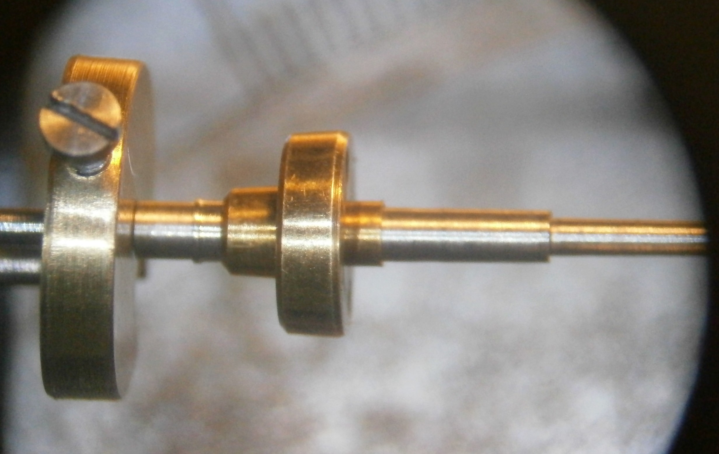
Figure 8: Balance collet on its taper.
The taper for the spring is dealt with next and after that, the dog is placed on the other end, the staff turned end for end, and the remaining two tapers finished to size. All is not lost nowadays if the seat is made slightly too small as an industrial adhesive such as Loctite 603 may be used to provide a permanent join, provided the gap to be filled is not too large. This cannot apply to the discharge roller of course, as it has to be adjustable, and should not be needed for the spring collet as the tolerance is large.
Now the pivots need to be polished and tradionally this was done using a Jacot tool, though the work can be done in a lathe fitted with a suitable tailstock attachment. All my technical dictionaries are silent on who devised this tool, but it was probably Henri Jacot, (1796 to 1868) who worked in Paris in rue Montmorency from 1833 with his brother Julien. On his death, the business was taken over by his nephew Albert Jacot.

Figure 9: General arrangement of a Jacot tool.
The set up is similar to that used for turning between centres, as shown in Figure 9, except that there is no tail centre. Instead one pivot rests in a groove of such a depth that part of the pivot projects above the walls of the groove (Figure 10), while the other pivot rests in a dead centre, about which the driver rotates. Again, the curved part of the pivot plays a part in locating the staff in the device. The correct depth of groove for a given pivot is stamped in hundreths of a millimetre on the end of the tool. In Figure 10 it is 20/100 mm or o.2 mm
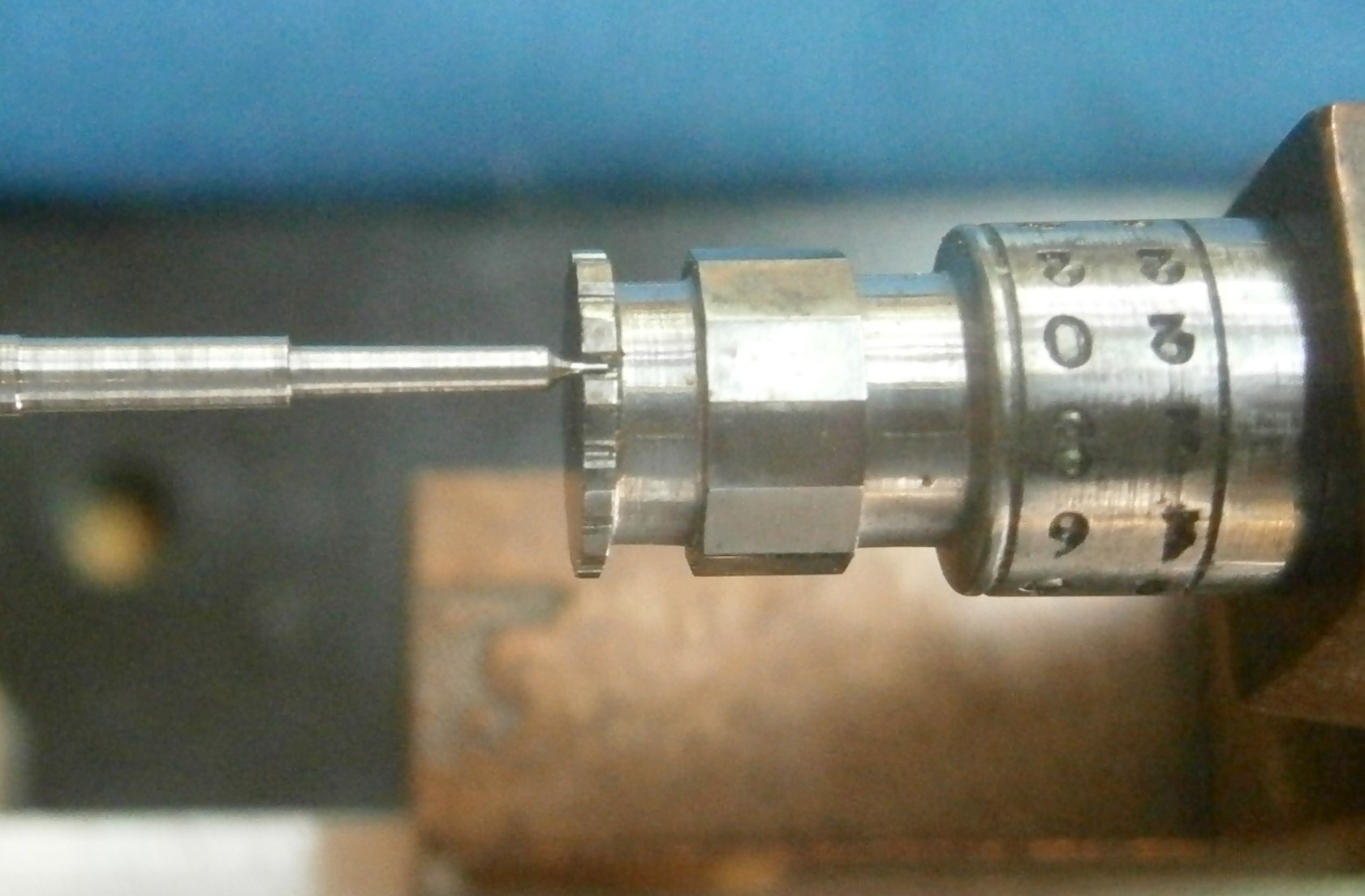
Figure 10: Close up of Jacot tool.
Note that most Jacot tools for sale are not large enough to accept a chronometer balance staff, so in mine I carefully milled a register parallel to the axis of the device in two planes. After cutting it into two pieces I could mount it adjustably on a bar to maintain alignment.
As the staff is rotated towards the operator, a burnisher that rests on top of the pivot is pushed away, smoothing and polishing the metal as well as keeping it in place in its groove (Figure 11). It is commonly stated that the process work-hardens the surface, but I doubt that the pressures attainable are sufficient for this. Polishing also reduces the diameter of the pivot slightly. The burnisher is a piece of dead hard steel in which very shallow transverse grooves have been made by dragging it across a piece of emery paper.

Figure 10: Burnisher in use.
The ends of the pivot are dealt with using a slightly different tool in the tail stock (Figure 11). Instead of grooves, the tool has a thin disc of steel with holes of various diameters to suit the pivot, so that as the staff is rotated, a burnisher can approach the end, to be manipulated in such a way as to slightly round the end. If this is overdone, a burr may be raised and if this happens, it can be simply removed by burnishing a slight chamfer.
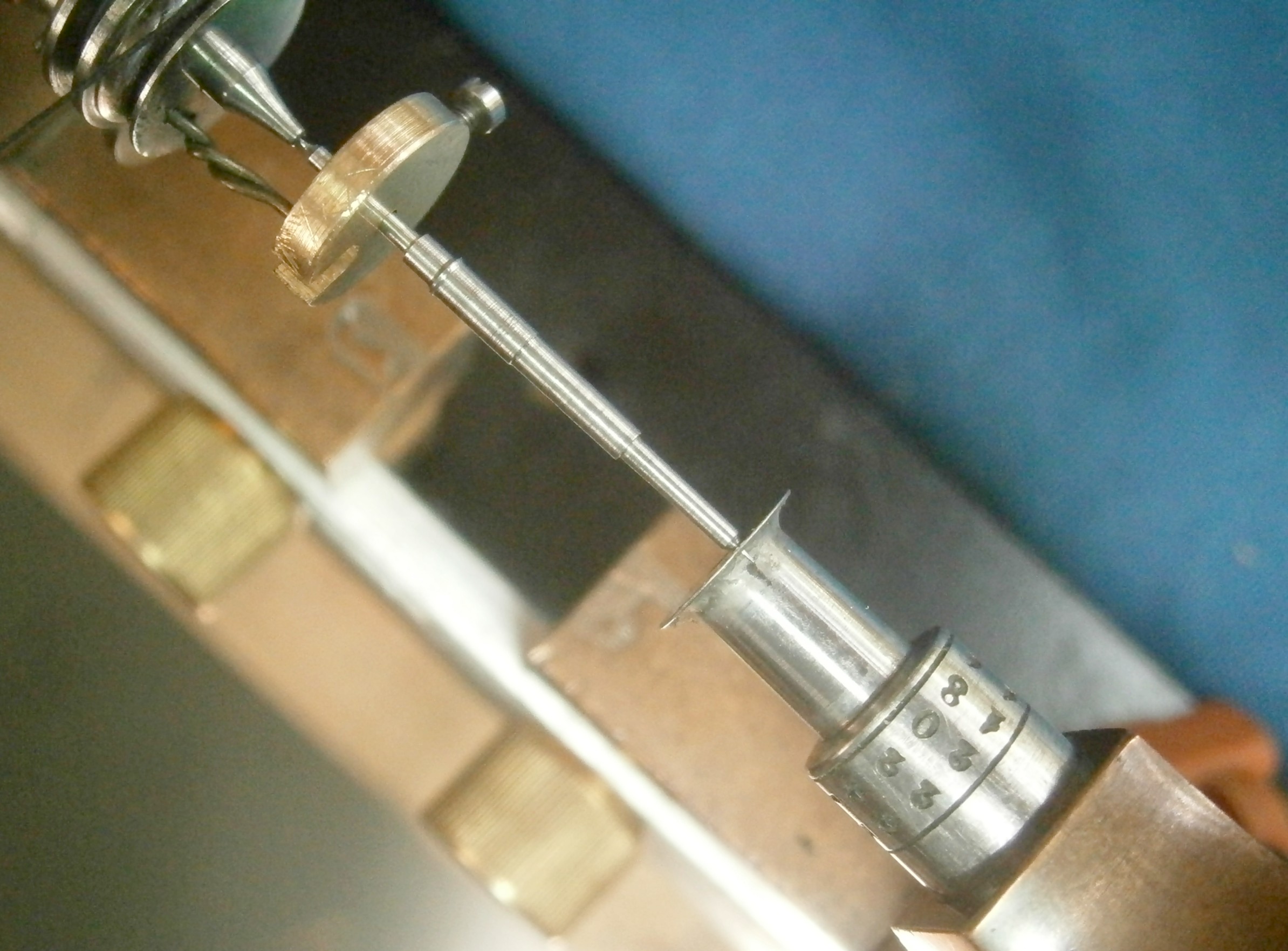
Figure 11: Jacot tool set up to burnish end of pivot.
Figure 12 shows the finished staff, together with the parts to be mounted on it (the spring is slightly distressed and will need more work on it). It is important not to hammer the rollers into place as this risks splitting them, especially the tiny discharge roller which will probably need adjustment anyway, once it has been tried in the chronometer. If a roller will not slide far enough along its taper by pushing it it into place, it is a simple matter to replace the staff between centres on the lathe and remove a whisker or two with a burnisher or very fine file or oil stone.

Figure 12: Finished staff with parts to be mounted on it.
I hope my attempts will help to illustrate one way how to make a balance staff and that too many experts will not be aghast at my methods. I am always happy to receive kindly worded comments, suggestions and corrections.

Leave a comment