In post number 30, I described how I made a new escape wheel for a Hamilton Model 21 chronometer and alluded to several other problems to be solved. In this post I will give a brief account of them, followed by a description of how I managed to avoid sourcing and buying a new impulse jewel. As the latter is tiny and rather difficult to photograph without sophisticated equipment, I apologise in advance for the sometimes poor quality of the photos, though I think they convey the details they are intended to convey.
As the fusee is one of the parts first to be removed, it revealed why I believe that the instrument had been dropped while out of its bowl (Figure 1).

Figure 1: Damaged chain track of fusee.
Near the top of the fusee, the walls of the chain track had been bent out of straight so that the chain was wedged in place. I gently eased the chain out of the track and then, using a small screw driver with all sharp edges stoned off, I persuaded the walls upright again and filed off tiny burrs with a fine Swiss file. The damage is no longer apparent.
All of the pivots of the escape and balance wheels had been sheared off and the state of their hole jewels attested to the violence of the fall that had broken them (Figure 2).

Figure 2: Destroyed hole stone of balance.
The plate jewels in the M21 chronometer are friction fitted into the plates and the throat of a staking set of normal size with the usual fitment for pressing jewels into place is generally too small to allow it to be used for a chronometer, so improvisation is needed to achieve a controlled pressure. I fitted the end stones first and then by careful and repeated measurement tapped the hole jewels into place with a brass drift until they were a scant 0.02 mm from touching the end stones. The official manual writes that they should be pressed into contact with the end stone, but it seemed to me that this might prevent the formation of an oil reservoir (if I am wrong, professionals please feel free to make a kindly worded comment). In retrospect I should probably have used a drift held in the tail stock of my small lathe as an improvised press with the plate resting on the face plate.
I have described pivot repairs in posts numbers 6 and 7.
In early M21 chronometers, the plates and the detent were made of nickel silver, a brass in which half of the zinc has been replaced by nickel to improve its mechanical and corrosion resistance properties. There is no silver in nickel silver, but it is a shiny white metal. Columbia Metals UK describes it thus: “Nickel silvers are capable of providing a unique combination of strength, high modulus spring properties, corrosion and oxidation resistance, …. and numerous other attributes combined with ease of forming, machining, plating and joining.” Later chronometers have detents of beryllium copper. Happily, in the disaster, which seems to have included running away of the movement, my detent was “bowed but not broken” and the passing spring had survived . The two photos merged into one of Figure 3 were taken on different days in obviously different lighting, but are of the same detent from different viewpoints.

Figure 3: Bent detent.
The top image shows the detent in its support block and the bend at the base of the spring is rather obvious. Less obvious in the lower image is that the bend is not symmetrical and has introduced a slight twist. Only a fragment of the locking jewel had survived. By this stage, I had removed the passing spring. A few words of warning may be useful here. The screw that secures the spring in place is the tiniest part in the whole chronometer and can easily be treated as a fragment of dirt and be lost, so it pays to store it safely in its own little container.
I straightened the spring by drawing it between the rounded jaws of special pliers, as described in post number 28 and eventually restored it to straightness. In an effort to avoid expense which I can ill afford, I attempted to make a new locking stone of tungsten carbide, as described in post number 24, for a Soviet MX6 chronometer, but the M21 locking stone is rather more slender at only 0.6 mm in diameter (versus 0.8 mm) and vibration from the belt of my tool and cutter grinder (since remedied) was enough to break it off when I attempted to grind the flats. I was thus obliged to buy a new locking stone and fit it as described in post number 15.
In early M21s the rollers were in one piece so that the mutual angles of the unlocking and impulse jewels was fixed, as in my example. Quite early on, the one-piece rollers were replaced by two separate parts. Figure 4 shows a view from a larger photo of the rollers from above, taken so I could replace them in their original position.

Figure 4: Roller and jewels.
At first sight, all appears well, but as repairs progressed I discovered that the impulse jewel was quite badly chipped, so much so that a “replace and hope for the best” attitude would have been a poor plan. Figure 5 shows the jewel after removal.
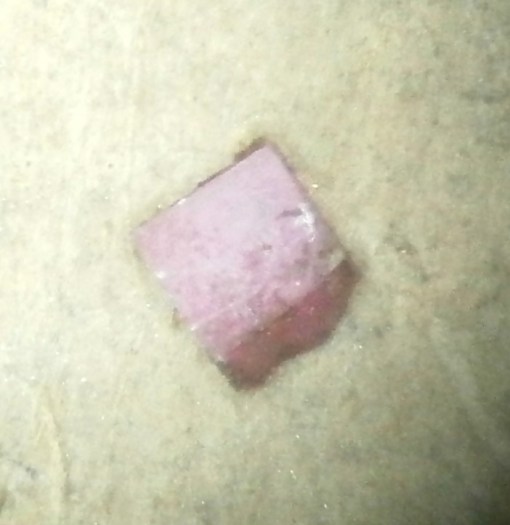
Figure 5: Chipped impulse jewel.
As I had not at that stage found a source of a new jewel, and doubted my ability to make a new one from tungsten carbide, I decided to reface it using a diamond file and laps, but first I had to devise a method of holding this tiny piece of synthetic ruby. I filed a notch into a scrap of 2 mm brass sheet using a warding file until the jewel fitted snugly, and then secured it in place by melting a flake of shellac over it (Figure 6).

Figure 6: Impulse jewel set into holder.
Note that this view shows that the damage extends quite a way down one edge of the jewel, so that in filing the new clearance the length of the jewel was quite considerably reduced. Looking through that most valuable of instruments, the retrospectoscope, I should have seated the chipped side in the holder and filed the new clearance on the other end. This would have maintained most of the length and made for a more secure re-fitting in the roller. A diamond file cut away the damaged face, much more easily than the same file cuts into tungsten carbide, and this underlines how much harder the latter is than ruby. As the clearance face comes into contact only with air, there was no need to achieve a very fine finish, but rather than leave a sharp edge, I rounded it a little with fine laps.
The roller is 6.35 mm (0.25 inch) in diameter, so another scrap of sheet brass with half of a 6.3 mm hole filed away provided the gauge to ensure that the tip of the jewel projected the correct length when being secured in place with melted flake shellac. This is described in post number 17.
Figure 7 shows the final position. Although the hold of the roller on the impulse jewel looks precarious, the shellac covers the base of the stone and I have left fillets of shellac on either face. If it does eventually give way, I will replace it with a carbide version.

Figure 7: Impulse jewel refitted.
The rest of the overhaul was routine and the chronometer showed no reluctance to resume its ticking with a very good action. However, I will end with a cautionary tale.
After about a week of rating it and finding that it had a very steady losing rate of about 1.7 seconds per day, its rate became erratic and then it lost two seconds overnight, so I stopped it and began to look for a source of the problem. As I was checking the balance and escape wheels for excessive end or side shake, the instrument suddenly declined to run at all. Suspecting that the impulse jewel had perhaps shifted, I removed the balance to check and found that it was still secure so I replaced the balance and turned my attention to the detent, to check what I already knew to be the case, that the escape wheel teeth were engaging about one third of the acting face of the locking jewel. The engagement was now much deeper. It was at this point that I discovered that, having at original assembly made a slight tweak to the depthing of the passing spring, I had failed to re-tighten the screw that holds the detent to the mounting block, labelled “detent clamp screw” in the original manual. Once I had tightened it, normal running resumed. Now I’m investigating its rate when half wound.

Leave a comment