To find your way to other posts click on October, 2016 in the list of dates on the home page. This will take you to a List of Posts and other suggestions on how to navigate the site.
Captain Dave of Sydney liked what I had done for his old Usher and Cole chronometer (post number 36) and so asked if I would overhaul another antique chronometer that he had, which was in working order but which was in a dirty condition. I was happy to oblige him, with my usual condition that I would accept no reward nor offer any guarantee. Figure 1 shows the face of the instrument in the condition that I received it,

Figure 1: Face of chronometer.
While some of the finer engraving had lost a little of its black wax, the silvering generally was in good condition and I elected not to interfere with it. Like a great many chronometers, sextants and fine clocks, the name does not necessarily indicate the maker as opposed to the retailer. Chronometer making during the nineteenth and early twentieth century was largely a cottage industry, with the “maker” putting together parts bought in from elsewhere, though the maker often was responsible for finishing and for adjusting the balance and escapement. According to Tony Mercer’s “Chronometer Makers of the World,” from 1906 onwards the movements for Kelvin and James White were made by Mercer, so number 7506 dates probably from late 1906.

Figure 2: Perhaps John and ?Thomas Travers’ mark on top plate.
The craftsmen who made the various parts often had no means of promoting themselves except by including a mark. We have seen in post 36 how George Cotton and Sons marked the mainsprings they were noted for supplying to Mercer and Kullberg among others. Until 1907, Mercer’s plates came from Prescott in Lancashire. Figure 2 shows the initials J&T.T on the top plate of 7506. John Travers (1849 to 1937), a distant cousin of Tony Mercer, had ten sons and the mark possibly includes one of them. Please correct me via a comment if this is wrong.

Figure 3: Condition of bottom plate.
Figure 3 shows the condition of the bottom plate and the top plate was in a similar condition. While no actual dirt is shown, one can see where oil has migrated onto the plate.
Figure 4 shows the dial side of the lower plate, where it can be seen that the pillars have been rivetted in place. This is probably a little more labour intensive than simply drilling and tapping the pillar for a screw and does mean that the two ends of the pillars are not interchangeable. Note too the collection of four punch marks to identify the plate. Apparently, they were routinely made in four pairs, sometimes with a fifth pair identified by an extra punch mark above the others.

Figure 4: Rivetted pillars and punch marks, bottom plate.
Figure 5 shows one side of the so-called English detent, and Figure 6 shows a general view from the other side. Making a detent was acknowledged to be one of the more difficult tasks and was a very specialised one. It was filed up from a solid block of steel and must have occupied many hours of work, with the expenditure of several files. A very high “black” polish was considered necessary, in which a highly polished surface looks shiny from a particular angle that changes suddenly to black when the angle changes.
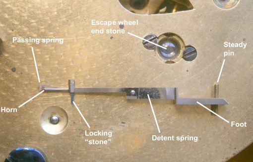
Figure 5: Horn side of “English” detent
I am unclear as to why such a high polish was thought necessary. Certainly, there should be no scratches on the spring that might act as stress raisers leading to failure, but a high polish of the rest seems to be due to tradition. No adjustment was possible of the depth of the horn or passing spring into the discharge pallet and the position of the passing spring on the horn had no adjustment other than one involving removal of metal. My next post will show how Mercers eventually made both relatively easily possible.
A disaster seems to have occurred at some time, as the locking stone is of steel instead of ruby. A L Rawlings in his “The Science of Clocks and Watches” describes how a chronometer having a hard steel impulse “stone” and dated to 1840 was working a hundred years later without any signs of wear of the escape wheel or the impulse face of the stone, and there seems to be no reason why the same should not apply to the locking stone. My own practice is to make a replacement locking stone out of tungsten carbide, which is both harder and stronger than ruby.

Figure 6: Passing spring side of detent.
Easily visible in Figure 5 and just visible in Figure 6 is the end stone of the escape wheel and it lies well below the surface of the plate. The reason for this became plain when I examined the upper pivot of the escape wheel (Figure 7).

Figure 7: Upper escape wheel pivot.
Probably as part of the same disaster that overtook the locking stone, the upper pivot had at some stage broken off and been replaced by a new pivot soft soldered in place in a pipe which was soldered into the escape wheel pipe. To many horologists this would be a terrible sin and there may well be better ways of tackling the problem, but the result in this instance functions well, if you like an engineer’s solution of which I feel bound to approve. However, the length of the arbor was shortened thereby and so the hole and end stones were lowered into the plate to compensate.
I find it nerve wracking to drill into an arbor, for if the drill jams and breaks off in the hole it is a minor disaster, which I prefer to avoid when it is possible to graft on a muff (See Post 7 of 23 July 2013). I now secure the muff with shellac rather than Loctite so that it is possible to make minor adjustments in length simply by softening the shellac with a soldering iron applied to the arbor. This is a good point at which to emphasise that one should always block the movement every time when making any adjustment to the balance that involves its removal, even when it seems to be unnecessary. I have had very good cause to regret not doing so when tired. The escape wheel ran away, shearing off the locking stone, bending the passing spring, buckling the detent and breaking the upper pivot.
In 1904, the Swiss, Charles-Edouard Guillaume, published his study on nickel steels “Les Applications des Aciers au Nickel,” the best known of which are Invar, which has a coefficient of thermal expansion of near zero and Elinvar, the elasticity of which remains practically constant with change in temperature. As his grandfather and father were watchmakers, it is perhaps not surprising that Guillaume soon saw an application of Invar to timekeeping. Prior to this, chronometers had a gaining temperature error between two temperatures at which there was no error, because the effective radius of a bimetallic balance reduced nearly linearly with increased temperature, but the elasticity of the spring reduced with the square of the temperature. Outside the two temperatures there was a losing error. There were many ingenious attempts to reduce this “middle temperature error” and 7506 has one of them due to Kullberg (Figures 8 and 9).

Figure 8: Auxiliary temperature compensation, from below.

Figure 9: Auxiliary temperature compensation, side view.
The outer ends of the rims are split to form, as it were, what I will call compensating arms. These arms carry auxiliary compensation weights, the outward movement of which is limited by an adjusting screw. With increasing temperature, the arms move in together, eventually leaving the end of the screws behind so that the moment of inertia is slightly decreased and the losing error compensated. With falling temperature the arms contact the ends of the screws and the rims and compensating arms act as one. With a suitable choice of temperatures at which there is no error, not only is the middle temperature gaining error reduced, but also the losing error in the higher temperature range.

Figure 10: Broken auxiliary compensation screw.
It is possible that someone misunderstood the purpose of the auxiliary compensation and thought that the tiny screws, about 0.8 mm in diameter, were for fine timing adjustment. Instead of leaving well alone, he twisted off the head of one of them, as shown in Figure 10. There was nothing left in which to cut a screw driver slot and so I attempted to grasp the inboard end of the screw with a fine surgical needle holder (Figure 11), grinding down the ends so as to enter the slot. I was able to get a firm grip on the end of the screw, but on attempting to release it only succeeded in breaking it off.

Figure 11: Modified needle holder.
As the only remaining solution was to drill out the remains, this was not a disaster and I was eventually able to drill out the remains by hand using a tiny self centring drill held in a pin vice. The drill wandered a little so I had then to re-tap the hole to a slightly larger size and make a screw to fit, leaving its tip in the same position as the one on the other side.
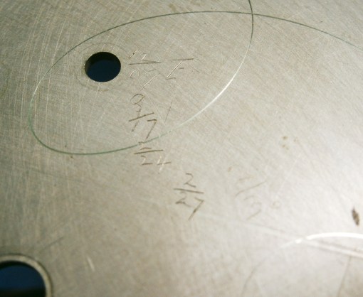
Figure 12: Overhaul dates.
The back of the face carries what I assume are dates of overhaul by the same person as the form of the digits is the same. It appears to have been overhauled in December 1909, March 1917, February 1924 and February 1927. A different hand has added faintly what is possibly February 1930. After cleaning and oiling I was tempted to add 12/19 with my initials, but resisted the temptation, as posterity owes me nothing.
I was able to adjust the rate to less than two seconds leaving further adjustment to Captain Dave, but my ambition to see how the temperature compensation fared at different temperatures was frustrated by a prolonged summer and the inability of my oven to cool over a greater range than 8 degrees Celsius (See postscript to post number 37).

Leave a comment