By double-clicking on them, most of the photos can be enlarged. Use the back arrow to return to the text.
While I have been fairly busy since January restoring sextants and chronometers, I have not been very good at writing blog posts and have some catching up to do. In early June, I heard from a new friend in Sydney who had in 2009 acquired a chronometer made by the makers Usher and Cole some time before July, 1897. The chronometer had never run since Captain Dave first owned it. A clock maker in Sydney had managed only to break off the minute hand. Could I help? I was happy to agree on my usual terms of every care taken but no guarantee given and no reward accepted, so later in June the instrument arrived at my home in Pukenui, New Zealand.
We know something of its earlier life, as it had been on trial at the Royal Observatory in Greenwich between July 3rd 1897 and 22nd January 1898 prior to being accepted for purchase by the Admiralty. It was described as having “Auxiliary to balance acting in heat and cold. Palladium spring”. Over the six month trial the difference between the least and greatest rate (a) was 19.4 seconds and the greatest difference in rate between one week and the next (b) was 5.6 seconds, giving it a trial number (a + 2b) of 30.6. Its least losing rate per week was -1.6/week and its greatest gaining rate was +28.1/week, not great by modern standards, but considered adequate in the days before the arrival of the Invar group of alloys. Bear in mind that by 1897, all Naval ships were steam powered and unlikely to be for a prolonged period away from ports where chronometers could be checked.
The chronometer duly acquired its broad arrow and disappeared from view until after the Second World War, when it was in use by the Australian Civil Aviation Department to check air navigation aids. Figure 1 shows its face before restoration to health.

Figure 1: Face on arrival.
The silvering was in poor condition. Note for future reference that it has stopped at 48 hours.
Problems
I quickly had it apart and found that as well as the broken minute hand, the upper escape wheel pivot was broken, the detent was in several pieces, the oil was green and of the consistency of thick glue and the mainspring had broken into three pieces at the barrel end.

Figure 2: Dead pivot.
Trials of re-pivoting
What should have been a relatively simple task of making a muff and applying it to the arbor (https://chronometerbook.com/?s=Repivoting+part+2) became a major problem when, during turning down of the arbor, it snapped off flush with the top of the pinion. I dealt with this by drilling right through the pinion, taking extraordinary care to ensure that the hole was well-centred and straight, and then making a complete new arbor to which I then glued the pinion with Locktite.
Carbide drills sold for circuit board work are sharpened by the four facet method which means that in principle they are self-centring, but if the tail stock of the lathe is not truly concentric with the axis of the lathe spindle, being brittle they will wobble and then break as the hole deepens. I use a stereo-microscope permanently mounted on my medium-size lathe and if there was the slightest sign of wobble, I adjusted the set-over of the tail stock until there was none, before drilling through. I have increased the rigidity of the drill to some extent with epoxy putty. Figure 4 shows the result before polishing and assembly.
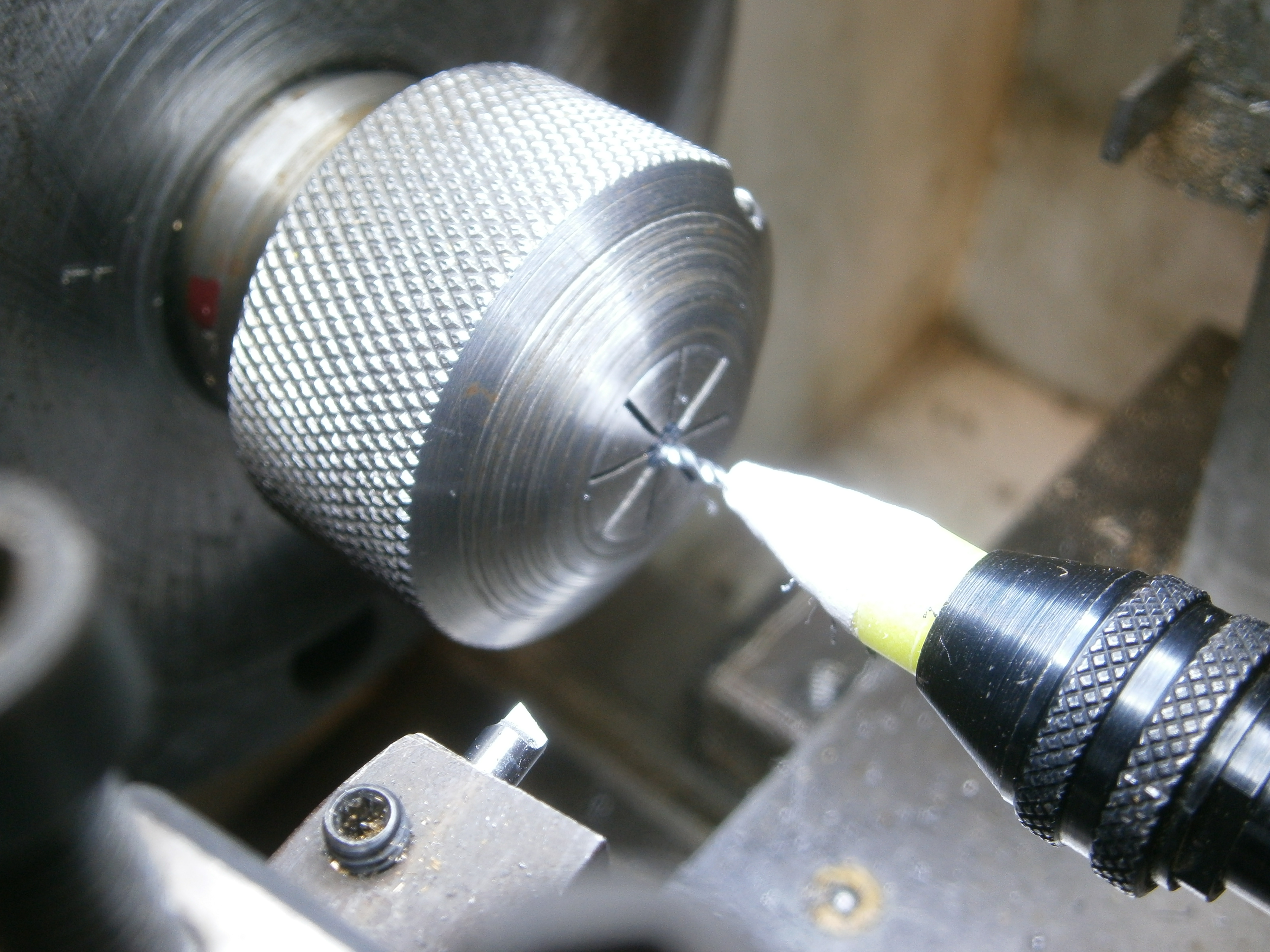
Figure 3: Starting centre.
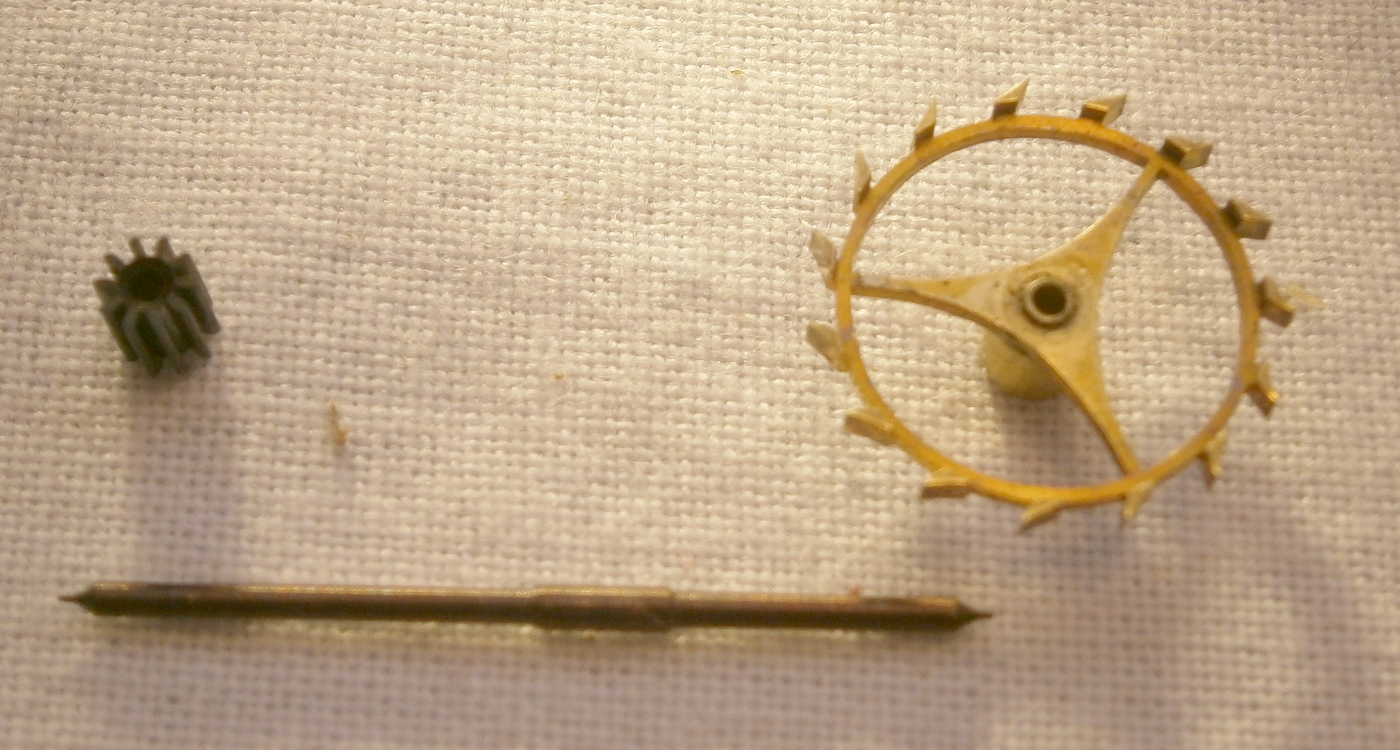
Figure 4: New arbor with pinion and escape wheel.
Of course, those handy with a graver might have used one to make a true centre before using a spade drill held in a pin vice and guiding it by hand through the pinion. I prefer to use the “iron hands” of the modern lathe to do the same thing, as I have not enough years left to spend them learning old techniques. Happily, both the pinion and the escape wheel ran truly after assembly.
New detent and support block
The detent posed a complex problem for an amateur like me, as the makers provided no means of adjusting its position on the top plate, but attached it directly to the plate. Figure 5 is a sketch from Marvin E Whitney’s “The Ship’s Chronometer” to show the general layout and dimensions of an English detent.

Figure 5: Means of mounting “English” detent.
Instead, and with Captain Dave’s permission, I elected to make a detent of more modern pattern and attach it to a support block so that its depth into the escapement could be adjusted by means of the screw seen on the left of Figure 6. See posts 22, 33 and 34 for details of making a detent.

Figure 6: Detent and support block.
Locking stone and passing spring
The locking stone had perished in the disaster that had destroyed the detent and the passing spring was absent, so I made the stone from tungsten carbide (see post 24) and the passing spring from 0.05 mm brass shim stock by the crude method involving fine scissors and finger nails described in the later part of post number 22.
Support block
I carved the support block out of a scrap of brass to the dimensions and shape of one from a Soviet MX6 chronometer (Figure 6). When it came to fitting it , I failed to notice that it overlaid the position of the third wheel arbor, and so had to file a cutout for the arbor. Once I had settled the position of the block, with the detent pointing to the centre position of the Balance wheel arbor (Figure 7), I clamped it to the top plate with a roughly made little clamp before spotting through for the steady pins and attaching screw (Figure 8).

Figure 7: Aligning horn of detent.
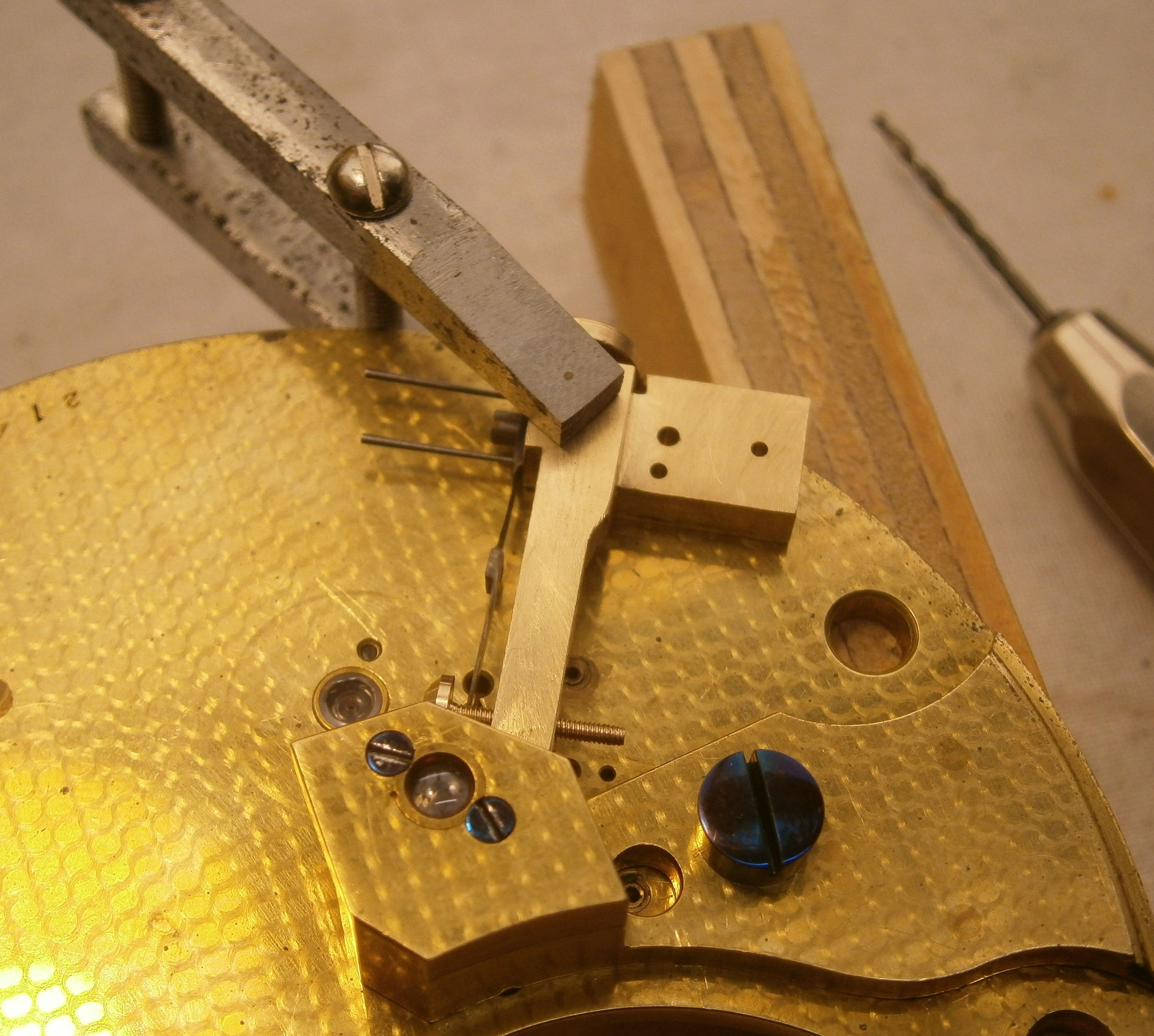
Figure 8: Mounting the support block.
Minute hand
Fortunately, both parts of the broken minute hand were present, so it was the work of only minutes to soft solder them together, leaving a generous fillet underneath where it cannot be seen.
Mainspring troubles
I next cleaned all the parts during which I discovered that the mainspring had broken into three parts (Figure 9). Until more modern steels were developed, this was a moderately common occurrence, so suppliers stocked a very large inventory of springs.

Figure 9: Mainspring, barrel and arbor.
I was interested to find the signature of the makers on the inside of the broken middle part and wondered whether this had perhaps been a stress raiser that contributed to the spring’s eventual failure (Figure 10). The whole of the inscription reads “Geo Cotton & Sons. Feb 1902”.
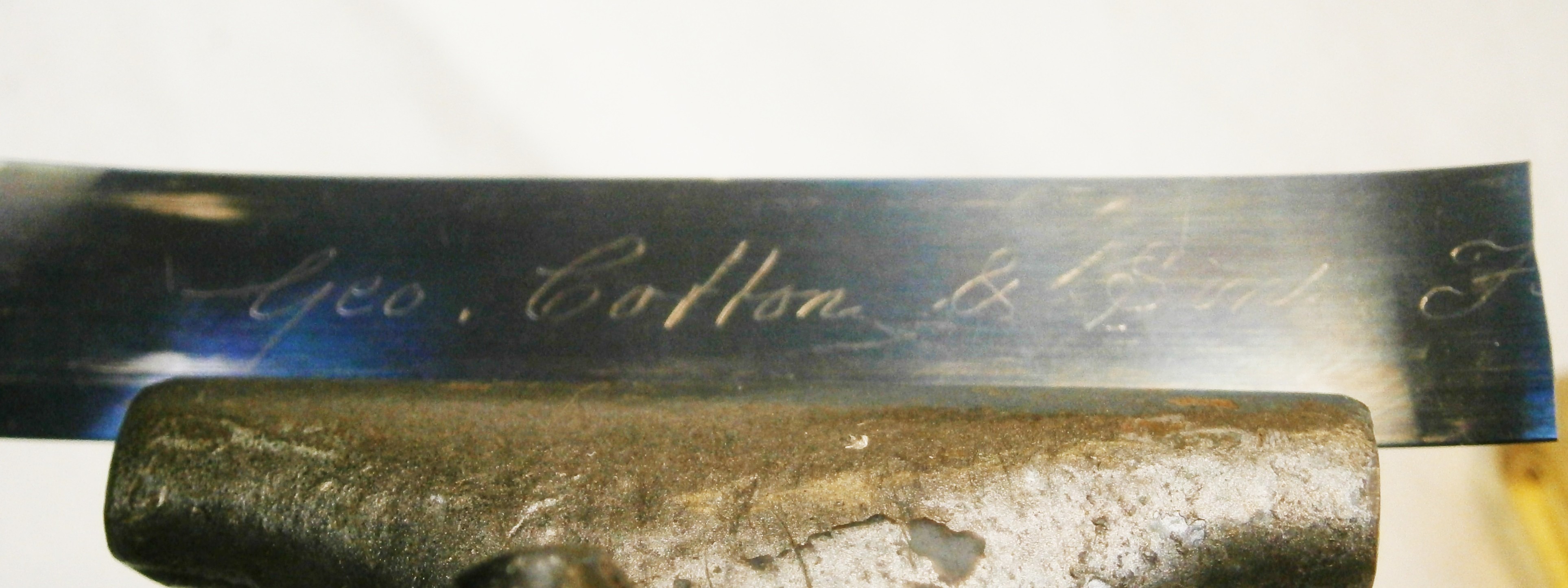
Figure 10: Spring maker’s mark.
I was able to obtain what was possibly the last spring of identical dimensions on the planet. I checked the length of the original spring with a tape measure and double checked by using the usual formula that takes into account the thickness of the spring, the internal diameter of the barrel and the external diameter of the arbor. They agreed with each other and so I cut the new spring to length with a few extra centimetres for good luck.
When it came to winding the spring to fit it in the barrel I was perplexed to find that I could not get the arbor hook to engage, try as I might to shape the inner end of the spring, and eventually discovered that the hook had lost its edge. There was not enough of the old hook to file it to a new hook, so I filed away the old hook and drilled a hole at 90 degrees for a new one. Once fitted, the outer end kept slipping of its hook, so I was obliged to remove it and fit a new one there as well.
All the parts were now ready to be assembled (Figure 11), I fitted them all together, set up the mainspring a cautious single turn and the tired old chronometer sprang into life at once. However, when I tried to set it up the usual six plus turns, I found that only five and a quarter were available and had to adjust the chain to make the stop work act earlier (about which, more later), lest a future owner wind it so hard as to rip the barrel hook out of its moorings. It then ran for a maximum of 48 hours, rather than the more usual 56 plus. In practical terms, this is insignificant, since two day chronometers were always wound daily at the same time.

Figure 11: View of top plate.
It seemed to be a pity to leave the dial as shown in Figure 1, so I stripped the old silver off, graining the dial in the process, using fine emery paper and refilled the engravings with sealing wax stained black (See post number 9). I used a proprietary substance , probably silver chloride, to re-silver, and stabilised it with cream of tartar. Lacquering clock faces is a skill that I have not learned, so I finished the face by polishing with silicone wax polish. I did the same with two clocks I made about fifteen years ago and the silver has not yet tarnished, though I live far away from any industry or busy roads, so this is perhaps not a good test of its efficacy. Figure 12 shows the finished face. Captain Dave learned a lot about polishing brass when an apprentice, so I left the bowl for him to do.

Figure 12: Re-silvered dial.
Now for some points of interest that do not appear in more modern chronometers.
Stopwork
If there were not some means of bringing winding to a halt, a ham handed person might well continue winding until the chain or the barrel hook gave way, so all clocks fitted with a fusee have some means of stopping the winding. Figure 13 shows the top of the fusee. The comma-shaped object is called a snail.

Figure 13: Fusee snail.
Turning now to Figure 14, which shows the underside of the top plate, we see the fusee iron, which is spring loaded to rest against the chain as it approaches the top of the fusee during winding. Eventually, the chain raises the iron to a position where the end of the iron butts against the projecting snail, bringing winding to a positive halt. Notice in passing that even the undersides of the plates have beautiful decoration, though only an overhauling chronometer maker would ever see it.
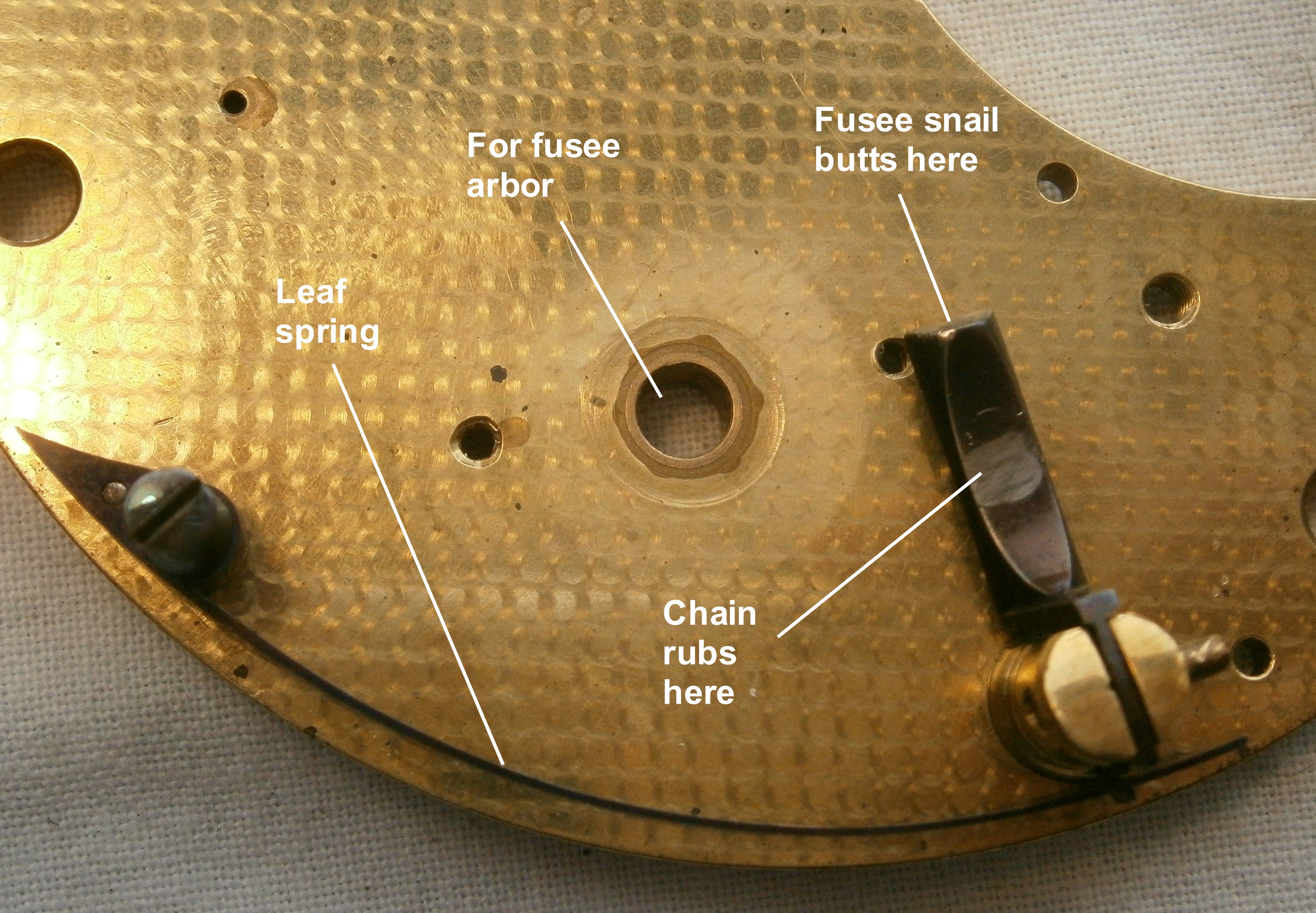
Figure 14: Fusee iron.
Auxiliary temperature compensation.
As the temperature rises, the material of the balance spring becomes less elastic and the chronometer tends to run slower. Meanwhile, the material of the balance rim has become larger, also slowing the chronometer., so the rim is made of brass on the outside and steel on the inside. Brass expands more with heat than steel and the effect is for the ends of the balance rim to move inwards, decreasing the mean radius of the rims and tending to compensate for the slowing effects of temperature. However, it was discovered that if the compensation is correct at two temperatures, the chronometer runs slower midway between them, the so-called middle temperature error. In other words a graph of compensation versus temperature is convex downwards.
Much ingenuity was expended in correcting for the middle temperature error to, as it were, flatten the curve to make it more linear. Figure 15 shows two such auxiliary compensations in the same chronometer. Poole’s acts at a given temperature at which it interferes with further expansion of the rim at lower temperatures, while Mercer’s comes into action at higher temperatures, when the short bi-metallic strip moves the weight inwards and reduces the moment of inertia a little. A much fuller description can be found in Rupert T Gould’s magisterial book, The Marine Chronometer: its History and Development.

Figure 15: Auxiliary compensation.
Charles-Edouard Guillaume’s studies of nickel-iron alloys led to the invention of Invar, which has a very low coefficient of thermal expansion and of Elinvar, which has a practically constant elasticity at temperatures likely to be survived by human beings. Combining Invar in the balance rim and Elinvar in the spring nearly eliminated the middle temperature error. For his studies, Guillaume deservedly won a Nobel prize in 1920. The Hamilton Watch Company’s invention of the ovalising balance further reduced compensation errors to a practical minimum.
Rate
How well did this old chronometer perform? Figure 16 shows its very creditable rate over 5 days, winding every 24 hours. There is a small deviation from the mean, a maximum of about one second at 70 hours, which would translate into a quarter of a nautical mile error in longitude at the equator. However, when allowed to run down to 48 hours, the losing rate changed to a gaining rate at about 30 hours, no doubt because the short mainspring began to deliver less power at this stage.

Figure 16: Rate over 5 days.
Maybe some of my methods would not gain the approval of all professional restorers, but I can say with Galileo Galilei “E pur si muove“, “And yet it moves”. And Captain Dave is happy too.

Recent Comments