(You can enlarge most of the figures by clicking on them)
In post number 22 of June 2016 I described my attempt to machine a spring detent, rather than laboriously filing it to shape and size. By post number 33 of September 2018, I had advanced to the stage of being able relatively rapidly to progress to the stage of having machined the detent all over, except for the spring. I had attempted, unsuccessfully, to surface grind the spring, and still relied on hand filing to reduce the machined spring to size.
At this point, Alan Heldman of Birmingham, Alabama kindly put me in mind of another method of finishing the spring to size, a method described on pp134 -137 by Robert J Matthys in his book “Accurate Clock Pendulums.” (Oxford University Press 2004). The method is described for making solid one piece springs for pendulum suspensions, and as these are typically 0.006 ins or about 0.15 mm thick, close to a typical 0.08 mm for detent springs, I though I would give his method a try. I have owned a copy of his book since 2006, but had never paid much attention to suspension springs.
Essentially, the method uses the side teeth of a small diameter end mill to reduce the spring to the desired thickness, supporting the reverse side using plaster of Paris. Using a Bridgeport vertical milling machine, a well-known full-size vertical milling machine, he found that he could not make springs thinner than 0.004 ins (0.10 mm) without tearing, using a brand new cutter, but I was hopeful that using my near-new Optimum Maschinen BF20V milling head and a brand new cutter, I might do a little better.
Having machined a detent as described in my last post, I set about making a simple jig to hold it while reducing the spring from a thickness of 0.3 mm to 0.08 mm. Figure 1 is a drawing of the jig. I made it from a piece of ground flat 3 mm gauge plate. One hole is tapped M1 for a screw to hold the foot of the detent and the other is a clearance hole for a little M1 brass screw to occupy the tapped hole for the foot of the passing spring. Note the 1.5 mm deep counterbores on the back of the jig (Figure 2). Tapping deep holes with small taps is fraught with the danger of breakage, while long screws lose their heads easier than short ones; and the counterbores mean that both dangers are reduced. I made the screws out of brass so that recovery from any disaster would be easier, but as it happened, all went well.
The jig is of a length to be held easily in a machine vice, whose fixed jaw must be carefully aligned with the X axis of the machine table, preferably by using a dial test indicator. It could of course simply be clamped to the face of an accurate angle plate.

Figure 1: Drawing of jig.

Figure 2: Rear of jig
Figure 3 shows the detent in place on the jig. The gap between the face of the jig and the spring can be seen clearly and the latter is without means of support against cutting forces. Matthys recommended filling this with plaster of Paris, known as POP to generations of orthopaedic surgeons until it was replaced by resin casts. POP sets quite rapidly, in a matter of minutes, especially if warm water is used, but then has little strength, but by 24 hours it has cured sufficiently for our purposes. It has the further advantage of setting to a solid from a quite runny mixture, so there is no difficulty in enticing it into narrow spaces.

Figure 3: Detent attached to jig.
Figure 4 shows the process complete. I have cleared plaster from the face of the spring and encased as much as possible of the rest of the detent to prevent damage from accidental tweaking of the horn

Figure 4: Plaster of Paris applied.
Figure 5 shows milling in progress. The cutter is a new 1.5 mm diameter, 3 flute titanium-coated end mill running at 2000 rpm. Matthys suggests a much lower speed of 325 rpm to reduce chatter, but it may be that there was wear or vibration in his milling head, as I noticed no problems with chatter marks. Aiming for a thickness of 0.08 mm from a starting point of 0.3 mm means that about 0.11 mm has to be removed from each face, so before starting to cut, I measured over the jig and the spring to give a datum. I then very gradually brought the cutter into contact, moving the workpiece back and forth as I did so. Once contact was made I very gently increased the length of the cut at each end until radii were formed, and at these positions I locked the table stops so I would not thoughtlessly advance the cut beyond and perhaps break the cutter, a particular risk when advancing to the left. A cutter of this size can take only small cuts in steel and I put on cuts of only 0.02 mm at a time, running the cutter back and forth, blowing away the fine swarf until no more formed and then measuring. The latter needs great care to avoid rocking, as the anvil of a micrometer can reach only the edges of the spring, and it must also avoid the radii at each end .

Figure 5: Milling cutter in action.
Figure 6 shows the finished appearance of the milled surface. When the detent is removed from the jig, most of the POP falls away and the remainder can be carefully chipped off, followed if necessary by brushing off the remainder under water. I found that the plaster caused mild surface rusting, so subsequently, before each encasing in plaster I dipped the detent in a dilute solution of shellac in spirit, drying it with a few seconds burst from a hair dryer. The almost immeasurably thin coat of shellac cured the rusting problem, did not affect machining and was easily removed by a few seconds of boiling it in alcohol.
It was easy to machine the second surface by simply flipping over the detent on the jig and symmetry at the ends was assured by the table stops.

Figure 6: Appearance of milled surface.
For preliminary finishing I attached the detent to a scrap of wood with plaster, which not only gave support to the spring, but gave better control than I can get using my finger nails to hold it (Figure 7). After removing machining marks from everywhere except the spring using a fine file, I hardened and tempered the detent as described in post number 22. The slight scaling that resulted I removed by a few minutes soak in dilute sulphuric acid (battery acid) followed by brushing.
To polish, I used progressively finer grit emery paper glued to a strip of wood, finishing with 1200 grit. This seems to give a bright finish and saves messing about with traditional pastes of diamantine. Twelve hundred grit is about 15 microns in diameter. It is now possible to obtain plastic film with fine diamond grit embedded, down to one micron size and a kind friend sent me some of various grits to try, though I find it difficult to attach it securely to a substrate. I will keep on trying.
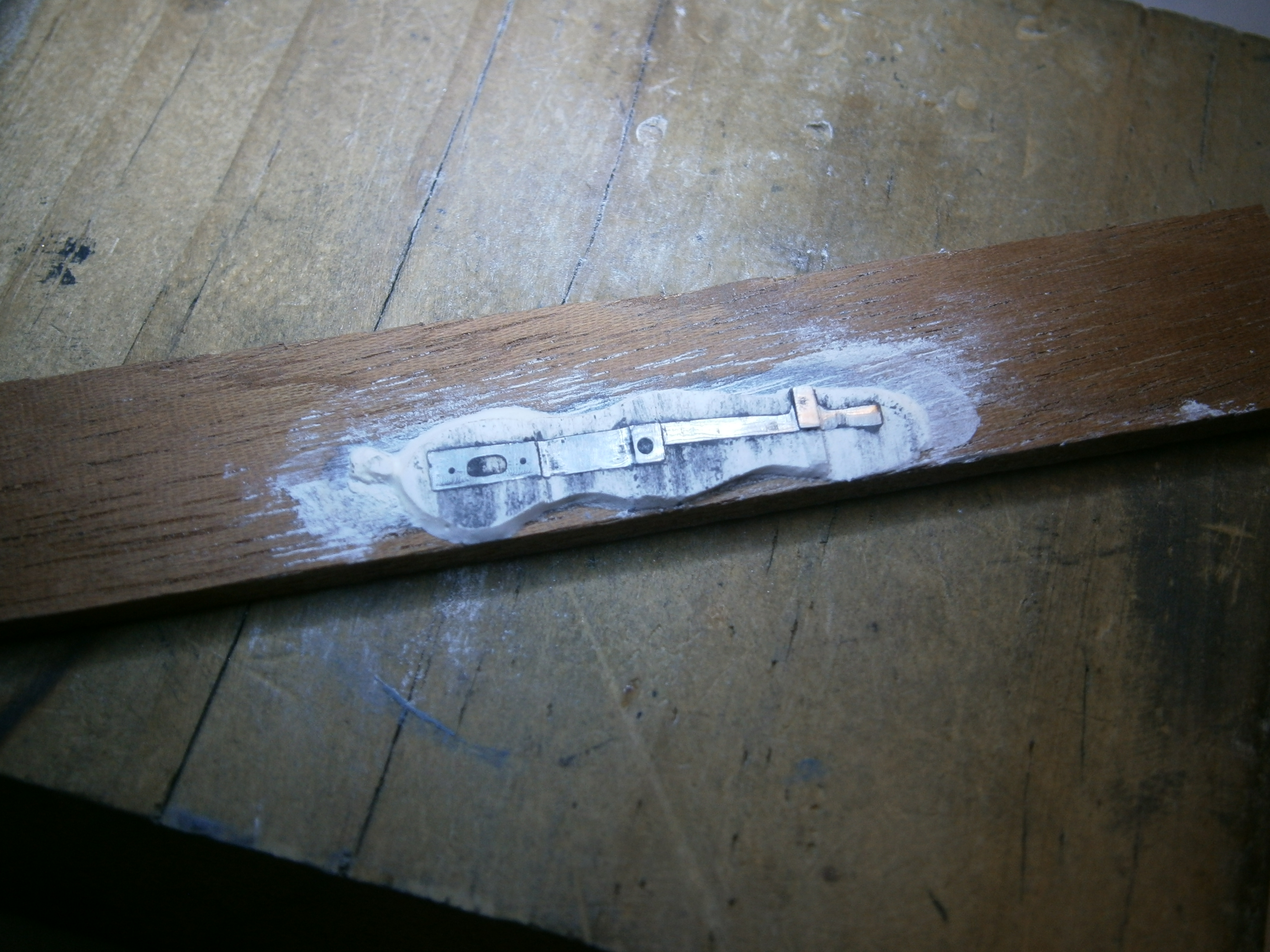
Figure 7: Detent embedded in POP to polish.
Figure 8 shows the final result. With magnification and after polishing there are fine longitudinal striations visible in the spring which represent minute imperfections in the milling cutter teeth, but as they are so fine I elected not to attempt their complete removal as they are not likely to be stress raisers. The radii at each end on the other hand reduce the danger of fracture. As far as I can tell, there is a slight increase in thickness from top to bottom of around 0.015 mm, due either to flexure of the milling cutter, or backward lean of the milling head. Since I checked for the latter only a few weeks ago, it is likely to due to the cutter.

Figure 8: Finished detent.
As always, I am happy to hear from readers who have constructive criticism or suggestions to make.

Recent Comments