A friend recently twisted off the square of the barrel arbor of one of his fine Soviet-era MX6 chronometers and sent me the remains to see whether I could effect a repair. While it would have been a simple turning job to reproduce a new arbor, getting the finish would not , as in the original, all arbors were chromium plated to a very hard and high polish, partly to resist corrosion, but mainly because combined with a bronze bearing, the friction from such a bearing is very low. For this reason, I decided to try a repair, and if it does not last, I will proceed to Plan B and make a new arbor. To this end I have taken off the dimensions of the original, which you can see in Figure 1 (you can enlarge all figures by clicking on them and return to the text by using the back-arrow).

Figure 1: Dimensions of arbor.
On examining the broken surface, it appeared that a brittle fracture had occurred, that is to say, fracture had occurred without any appreciable deformity having taken place, leaving a cobble-stoned appearance to the fracture surface (Figure 2). Testing with a file confirmed my suspicion that the the arbor had been hardened all through and left very hard. While this would increase its strength to some extent, it would make it more liable for a brittle fracture to begin from a scratch, a nick, or even a sharp corner, and this fracture had begun at a sharp corner between the squared and circular portion of the shaft.

Figure 2 : Fracture surface.
Before being able to machine the remaining arbor, it was necessary to soften the end by heating, while trying to prevent the spread of heat to the rest of the arbor. I did this using a small blow torch while holding the arbor in a vice-grip clamp to act as a heat sink. Once I had done this I was able to face off the end, centre drill it and drill the end 3 mm diameter with a freshly sharpened drill, to ensure as far as possible that the hole would not be oversize due to un-equal sizes of the cutting edges. However, at about 4 mm depth, the drill began to protest as it headed towards the 10 mm diameter and I was forced to stop drilling at a depth of 5 mm, as the centre of the arbor had remained too hard for the drill.
Next came the new square, which I made from silver steel, a high-carbon water-hardening steel which in the soft condition has a bit more strength than ordinary mild steel. To begin with, I turned a 60 degree cone on the end of some 4 mm diameter stock and set it up in my small dividing head, supporting the cone on a female tail centre (Figure 3).
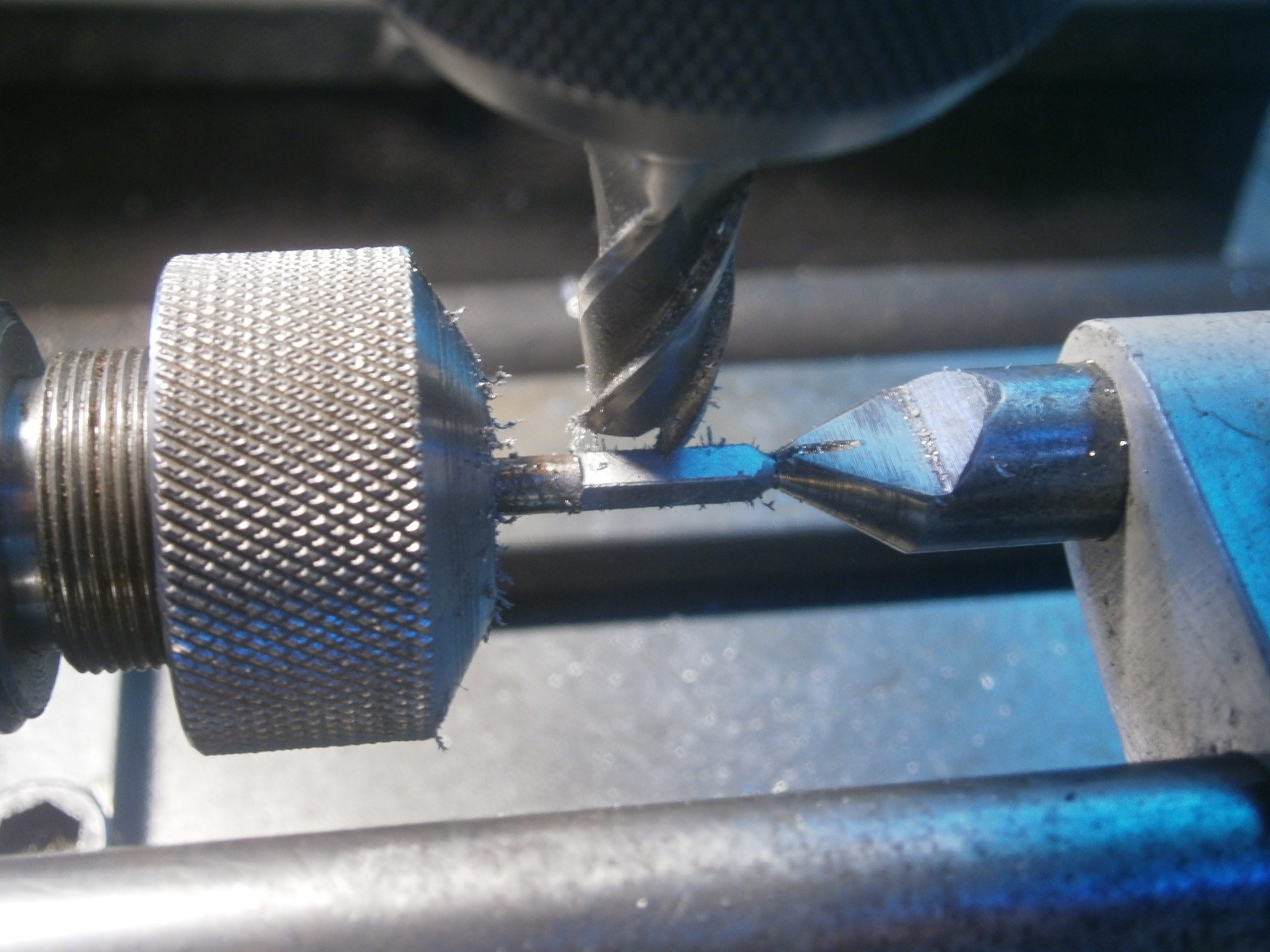
Figure 3: Producing the square.
It was then the work of minutes to cut the four flats with a milling cutter, measure the distance across the flats and then to take a finishing cut to bring the new square to size. As a final check, I tried it in the key.
I then had to return the work piece to the lathe, to turn down a portion to 3 mm to fit the hole drilled in the arbor (Figure 4). While I could check the dimensions of the round part for size with a micrometer, it was not possible to try it in the hole before parting off, and if the hole had been over-size, I would have been obliged to make another square. Looking through that very useful instrument, the retrospectoscope, I could have made a little gauge to try in the hole and turned down the new part to the size of the gauge, but in the event, the shaft fitted the hole snugly.

Figure 4: Turning down to 3 mm.
How then to secure the new square in the hole in the arbor? In large-size work in times past, the shaft would be turned over-size and the part with the hole in it heated to expand it until the shaft could be pushed into the hole, which would then grip it as it cooled. This was a typical way to secure steam locomotive wheels to their axles. In smaller sizes, a holes might be drilled through the two parts for a pin to prevent rotation and in clock work, the hole might be machined tapered and a matching taper turned on the shaft. The two parts would then be ground together until they seized.
Happily for me, modern industrial adhesives such as Loctite have made these processes obsolete. The adhesives cure in the presence of moisture and absence of oxygen, joining the part securely. I am a little doubtful whether there is a sufficient area of grip between the two parts and would have liked to drill the hole deeper. Time will tell. Figure 5 shows the finished repair.

Figure 5 : Finished repair.
The method of forming the hook is of interest. Classically, a raised band would have been left in the middle part of the arbor and laboriously filed down to form a hook. In this arbor, a 2 mm cross-hole has been drilled for a round piece of hardened steel on the end of which has been formed a hook. This method as well as being easy and saving time, allows the projection of the hook to be carefully adjusted to that it projects only as much is necessary and allowing the central part of the spring to conform snugly to the arbor. I imagine that it was glued into place.

Recent Comments