A marine chronometer must never be wound clockwise except for those few that have a winding square on the front or side of the instrument. Winding in the wrong direction risks damage to the maintaining power mechanism and, if reverse power should reach the train, the locking stone and detent may be damaged. For this reason, all makers provided a key that would wind only in an anti-clockwise direction and which would slip if clockwise winding was attempted, rather than rely on the user’s memory. They are often referred to as “tipsy keys.” Most have a spring-loaded dog clutch, but many German Einheits-chronometers (Standard chronometers) and the Russian MX6 chronometers which closely followed their construction used a spiral spring which tightened and gripped the winding shaft of the key when turned anti-clockwise but which slipped when turned clockwise. This latter type is much easier to reproduce than the dog-clutch type and as second-hand chronometers, especially those sold without their cases, are often lacking a tipsy key, the collector is obliged either to source a new key on the internet or to have one made. One maker proposed a charge of 150 British pounds a few years ago, which seems rather a lot. This blog gives the details of one way to make a tipsy key and it may serve as a guide to others.
Figure 1 is a general arrangement drawing which no doubt violates many conventions, but which I hope makes the structure clear. 1 is the winding shaft with a square hole down the end. It is gripped by a helical spring, 5, which is a close fit over the shaft but an easy fit in the body, 2. The helical spring, which is anchored in a hole in the body at one end, must have a clockwise spiral if it is to grip the shaft when it is winding anti-clockwise. 3 is a knob, in this case a simple disc, but can be of any shape that takes the fancy. 4 is a taper pin that hold the knob in place and restricts the outward movement of the winding shaft. It is reamed after drilling the cross holes through the body and knob with the latter in the correct position. The drawings and photographs may be enlarged by clicking on them. Return to normal by using the back arrow, at top left on most browsers

General arrangement sectional drawing.
Figure 2 is a drawing of the several parts with dimensions added. These of course may need to be varied to suit a particular chronometer, but should work with the majority of chronometers made in the twentieth century. For those not used to reading drawings, the main view is a plan view and the view to the side is what one would see standing on that side looking back.
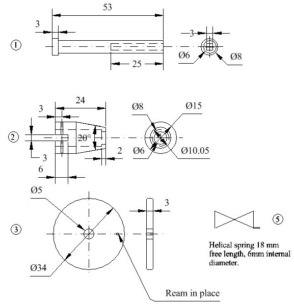
Figure 2: Dimensioned drawing of parts.
Making the shaft.
This begins by facing a length of 8 mm brass rod, centring it and drilling it to a depth of 25 to 30 mm to a diameter that is the same as the across-flats dimension of the required square (Figure 3). The rod needs to have a length allowance to allow it to be gripped securely in the lathe chuck. The deep hole allows one room to manoeuvre when converting the round hole to a square one, using a square Swiss file. You file away, using the remnants of the hole as a guide to when the square is near to size and then try it on the chronometer. Once it begins to enter, it is then simply a matter of raising the filing hand a little so that the square is deepened until 4 or 5 mm will grip the winding square (Figure 4).

Figure 3: Facing, centring and drilling.
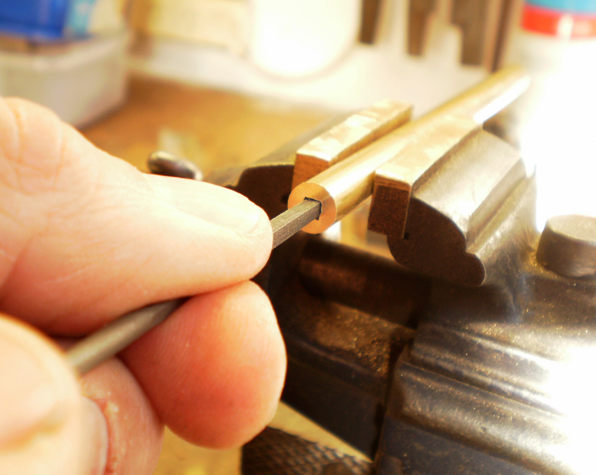
Figure 4: Converting a round hole to a square one.
The proto-winding shaft is then returned to the lathe, the end supported with a back centre, the 6 mm portion turned down to size (Figure 5) and the whole parted off to length (Figure 6). The diameter may of course be adjusted a little to suit available springs. Most seem to be wound anti-clockwise, so your collection of odd springs may have only a few that are clockwise helices.
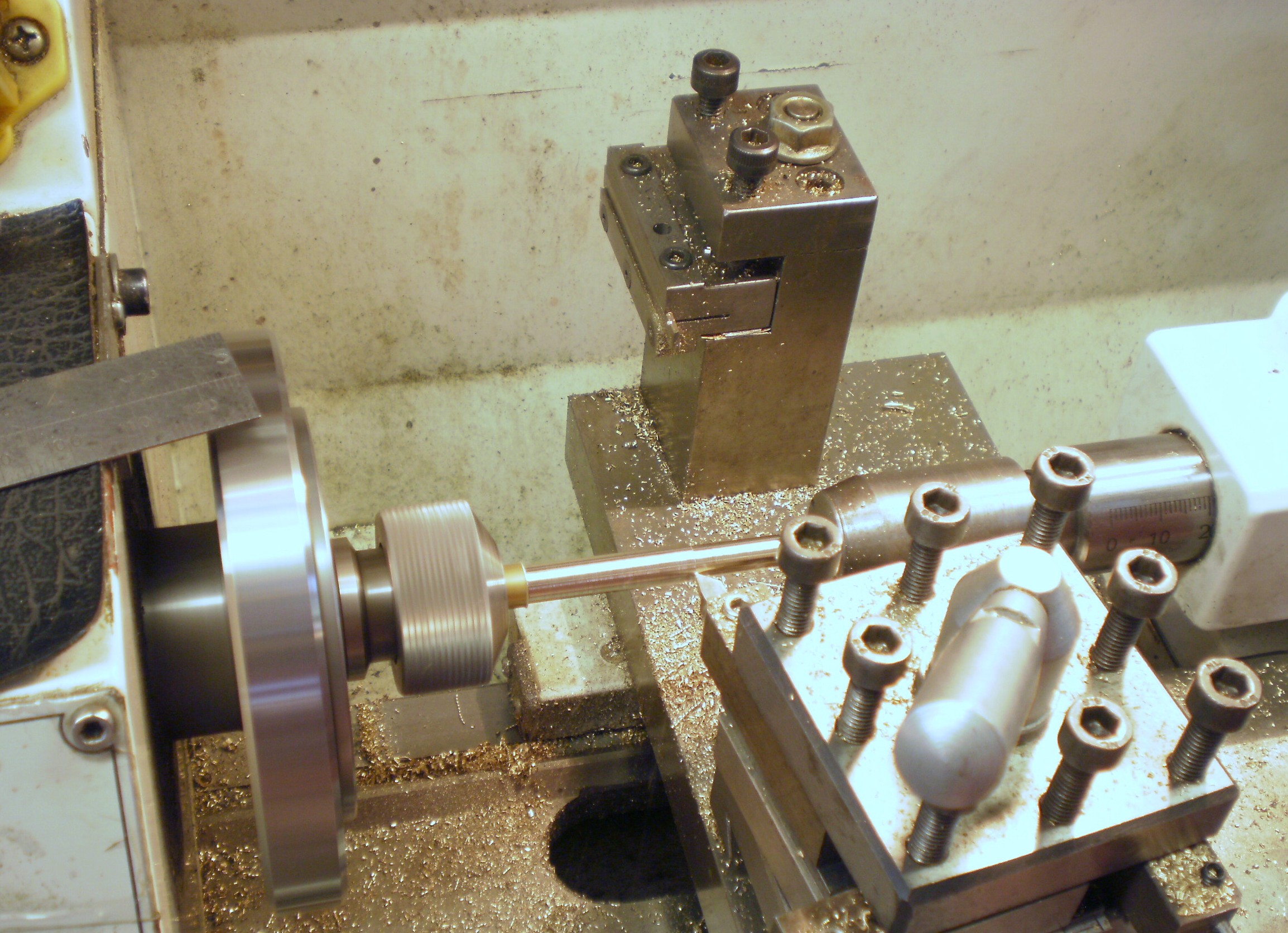
Figure 5: Turning to size.

Figure 6: Parting off.
The Body
Making the body is mainly a straightforward drilling and turning exercise, but before parting off from the parent metal, a 3 mm wide slot must be milled across a diameter for the knob (Figure 7). The home workman is more likely to use a slot drill for this, but those well equipped with a horizontal milling machine and a suitable cutter may choose to use this, though the setting up time is probably longer. Of course, the job can also be done with a saw and file.

Figure 7: Milling slot for knob.
After parting off, the nose is tapered, as shown in Figure 8, taking care to taper the correct end!
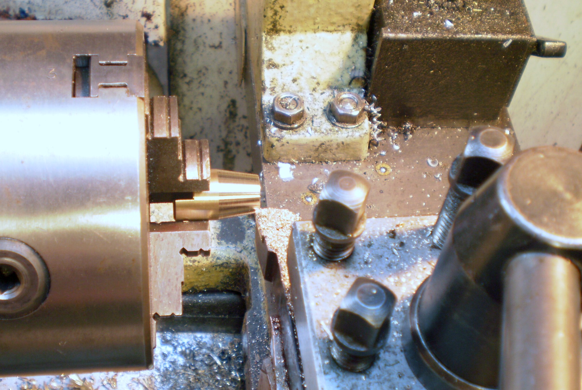
Figure 8: Taper turning nose.
Then, using a drill of about 0.8 mm diameter, a hole is drilled which will anchor the lower end of the spring to the body (Figure 9).
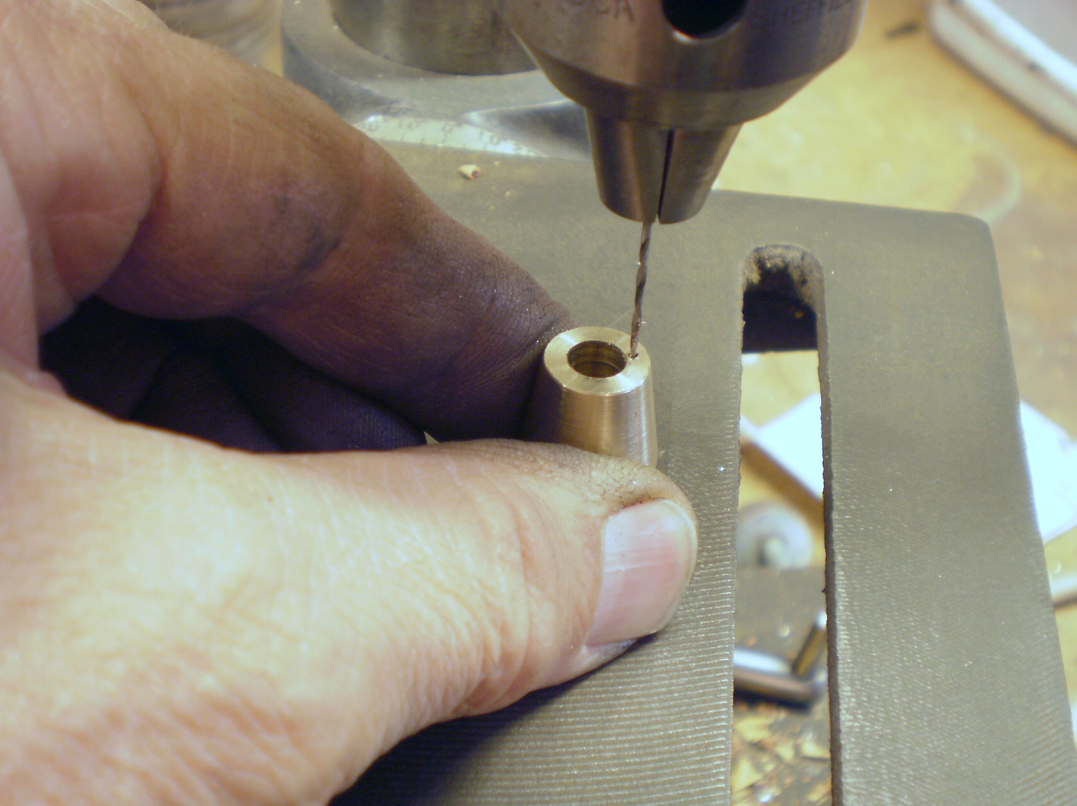
Figure 9: Drilling for spring anchor.
The Knob
The disc-shaped knob could be parted off a brass bar 36 mm in diameter, leaving the problem of how to finish the parted off face, so it is much simpler to make it out of sheet material. Those who like exercise can saw it to approximate shape and then file it round using a suitable cheater (see previous post for a note about these useful items), but I chose the easy way of mounting a square on a mandrel and turning off the corners(Figure 10). The edges can be bevelled at the same time.
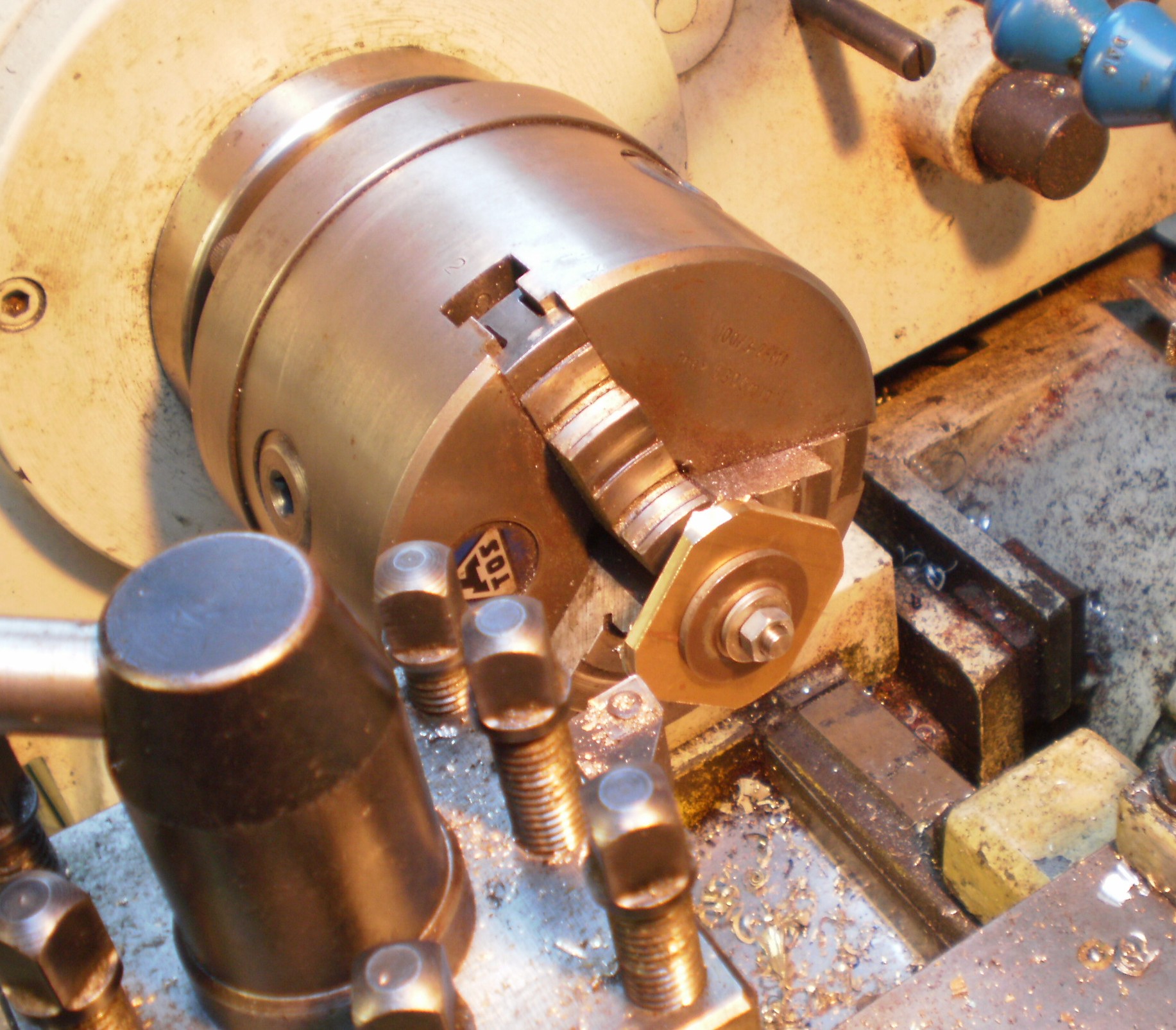
Figure 10: Forming the knob.
The knob is then held in the slot to be cross-drilled and reamed for a taper pin which will hold the knob in place (Figure 11). Taper pin reamers receive little use in industry these days and may be hard and expensive to find, so a parallel pin secured with a dab of industrial adhesive such as Locktite will do just as well.
Figure 12 shows the parts ready to be assembled. The compression spring shown is not ideal as the end tends to jump out of the anchoring hole, but it was the only suitable clockwise spring I could find at the time. I have since replaced it by fitting an anticlockwise extension spring over a 6 mm mandrel and unwinding it. I then cross drilled a hole in a 4.75mm (3/16 in) mandrel to anchor the end of the 0.7 mm wire and rewound the spring, clockwise.
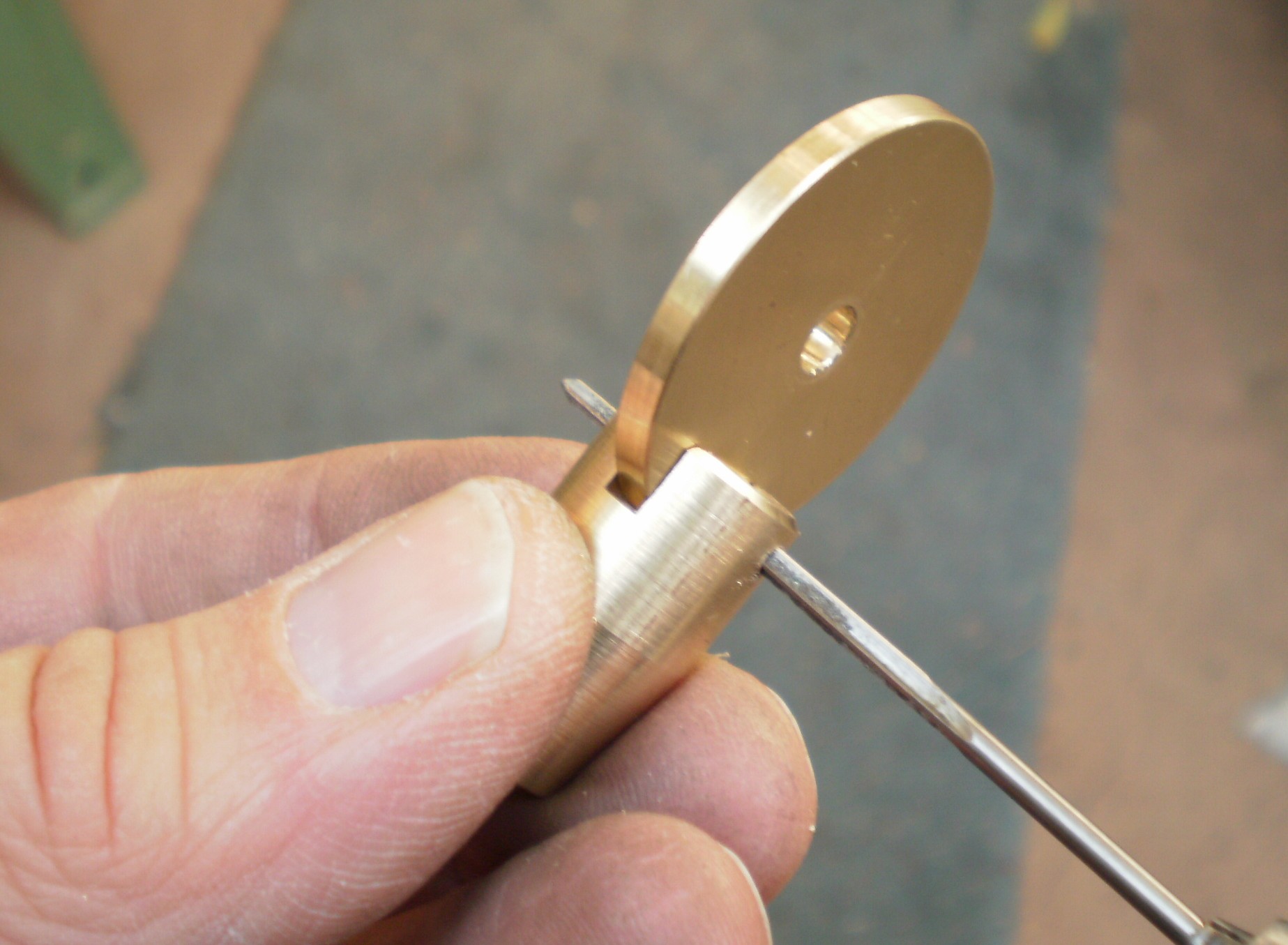
Figure 11: Reaming for a taper pin.

Figure 12: Exploded assembly.
After cleaning up the parts are assembled, tapping the taper pin lightly home and sawing it off to length. A brass pin would have been ideal, but I made do with a steel one, as the chronometer it is intended for will never go to sea again. Figure 13 shows the completed key.
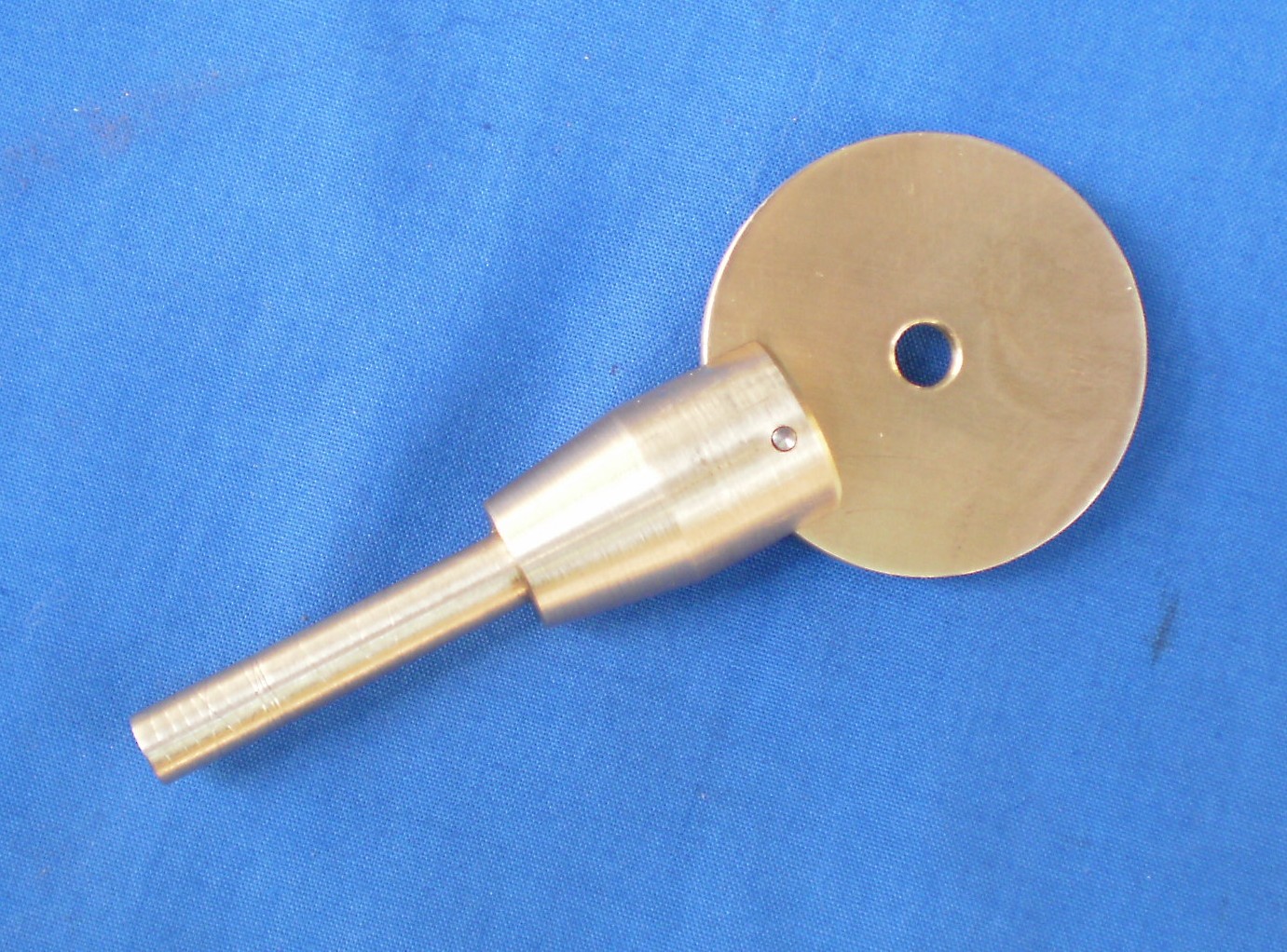
Figure 13: The completed key.
If you enjoy reading this or other of my posts, let your interested friends know so that I will be encouraged by visitor numbers to write more. And of course buy “The Mariner’s Chronometer” for much, much more.


Recent Comments