A note on finding your way around this site: If you know what you are looking for, you can enter a search term in the search box. You can also look in the “List of Posts” to get a date and either click on that date or enter a search term.
In my post Number 8 of July 30, 2013, I wrote about how to make one form of tipsy key. Recently, to amuse myself, I have bought shipwrecked chronometers and tried to bring them back to life. Currently, I am working on a Hamilton Model 21 chronometer which seems to have been dropped, probably while out of its bowl, as all the pivots of the balance and escape wheels are broken and the track on the fusee for the chain has been damaged. Two of the hole jewels of the escapement are also badly chipped and the locking jewel has been broken. While waiting for replacement jewels, I have occupied some time by cleaning the rest of the chronometer and making a new key for it. Since a lot of time is spent setting up for machining parts, it is sometimes almost as quick to make two parts as to make one and this is what I did.

Figure 1: Key fashions.
Figure 1 shows two tipsy keys that use clutches to prevent winding a chronometer clockwise. The one on the left is from an antique Mercer chronometer that perished when the Australian city of Darwin was largely destroyed by Typhoon Tracy in 1974 and the one on the right is from a German Einheits-Chronometer of 1943. The latter still keeps an excellent rate.
Figure 2 is a composite drawing of the interior mechanism of the second key, while subsequent drawings of the separate parts give the dimensions of the parts as I made them. I had to alter some of the dimensions of the knob so as to use what I had available in the way of brass stock, but as long as the square hole fits the winding square of the chronmeter, the dimensions do not have to be identical to the original.

- Figure 2: The interior of the key.
The clutch teeth on the end of the winding shaft inside the conical body are held in engagement with the teeth on the knob by means of a short helical spring. The teeth are sloped so as to slip if the knob is turned clockwise but to engage if turned anti-clockwise.
It is a simple turning exercise to make the shaft (Figure 3), by turning down a piece of 8 mm stock to 6 mm, drilling the end to a depth of about 25 mm to a diameter equal to the across-flats dimension of the chronometer winding square, and parting off.
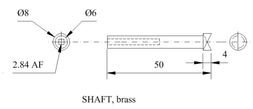
Figure 3: Drawing of shaft.
The round hole then serves as a guide to convert the round hole into a square one, while the depth of the hole allows a square needle file to get a decent grip on the metal. The nearly completed filing is shown in Figure 4. Of course, those lucky people who possess small broaches could use them and it is also possible to drill square holes with an appropriate attachment to the drilling machine.

Figure 4: Converting a round hole to a square one.

Figure 5: Body drawing.
For the body, I turned down a piece of 20 mm round brass bar to 18 mm, drilled and reamed the centre hole to 6 mm and followed the 6 mm hole with an 8 mm slot drill to form a flat-bottomed hole as shown in Figure 6. As I was making two keys, for each tool set up I switched ends of a length of bar.
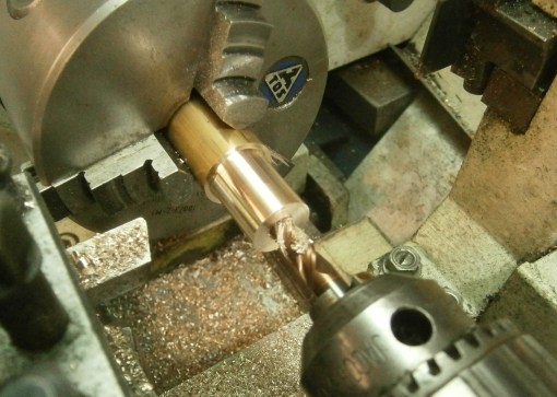
Figure 6: 8 mm hole counter-bored.
The top slide is then set over to 12.5 degrees and the conical outside generated (Figure 7), before parting off to length. Technically, I suppose the shape should be described as a frustrum of a cone.
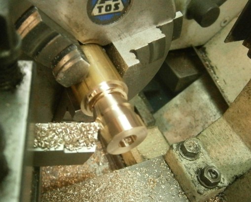
Figure 7: Generating conical shape.
I postponed drilling and tapping the M3 (or 6 BA would do) holes until the knob was made. Thirty millimetre stock would have been better than the 26 mm I used, as it would have given me a key with a bit more leverage.
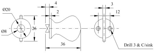
Figure 8: Knob drawing.

Figure 9: Turning diameters of knob.
Making the knob begins by turning the 8 and 20 mm diameters shown in Figure 8. The bar is then set up in a vice on the milling machine to form the flat parts of the knob (Figure 10). This is perhaps a good spot to point out that tools for cutting brass need to be sharp and preferably reserved for use only on brass, as once they have been used on steel they tend to skid over brass.

Figure 10: Milling flats.
The second flat is formed by rotating the bar through 180 degrees and checking with a micrometer that the surfaces are parallel before making the final cut on the second surface. While it was still attached to the bar, I used a simple template to mark out the complex shape (Figure 11), before cutting around it using a piercing saw. No doubt it could be machined using some sort of computer-aided process, but with a little practice and a sharp saw blade it is much quicker to cut it by hand and finish off with sharp files.

Figure 11: Using template to mark out for sawing to shape.
This is perhaps a good moment to drill holes at tapping size for the screws in the knob. They will be used to spot the holes in the body and then enlarged to a clearance size later.
Next comes the machining of the clutch teeth, and it needs some thought and care to make sure that they slope in the correct direction! The knob can be held by the flats in a machine vice that tilts. I guessed that the teeth tilted at 30 degrees, but 25 degrees would have given more clearance for the side of the 3 mm diameter end mill at the end of its cut (Figure 12).
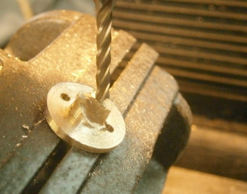
Figure 12: Clutch tooth being formed.
The same set-up is used for the teeth on the end of the shaft, as shown in Figure 13.
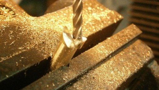
Figure 13: Milling teeth on shaft.
After cleaning off burrs with a fine file, the key can now have a trial assembly and a spring cut to length so that the teeth are held in engagement and that there is enough free space for them to slip when turned clockwise.
Drilling for the tapping holes in the body presents minor problems, as its shape prevents it from being held in a vice. I got around this by assembling the key, holding the shaft in a drilling vice and rotating the body until the teeth were locked, then drilling the hole to full length. Though brass is traditionally cut dry, it is a sound plan to use a little lubricant when tapping the holes, as there is a tendency to jamming unless the taps are sharp. Most of us cannot afford to keep two sets of taps, one for sole use on brass, so a little lubricant may save a lot of heart ache due to a work piece having to be scrapped because a broken tap is jammed in it.
A little grease and assembly with a couple of countersink-head screws completes the key (Figure 14).
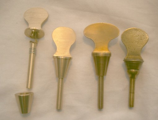
Figure 14: Two new and two old.
I hope this account was of interest to you. You will find much more about marine chronometers in my book. Take a look at “About the Mariner’s Chronometer”.

Recent Comments