With the exception of Figure 1, all figures may be enlarged by clicking on them. Return to the text by using the back arrow.
I have long been aware that the Hamilton Model 21 chronometer had a version with four orbits, that is to say that as well as the usual minute hand it had four subsidiary dials: the usual seconds and power reserve dials with two extra ones to show 24 hours and the days of the week, shown in Figure 1 (I have been unable to trace the source of this photo). The movement of the chronometer is the same as standard, but the motion work, the system of pinions and wheels behind the face that drives the hands, is different. Only 27 were made and were designated Model 221. One sold in 1982 for $6,600, underlining its rarity.

Figure 1: Hamilton Mod. 21 four orbit face.
When navigating in the vicinity of the International Date Line it is surprisingly easy to take out data from the Nautical Almanac from the wrong day of the week, and on long voyages across the Pacific, when tired, it is also possible to get the Greenwich time wrong by twelve hours. At least, I gather that this was the ostensible reason for making a four orbit version. However, seafarers are a conservative lot and the idea never caught on.
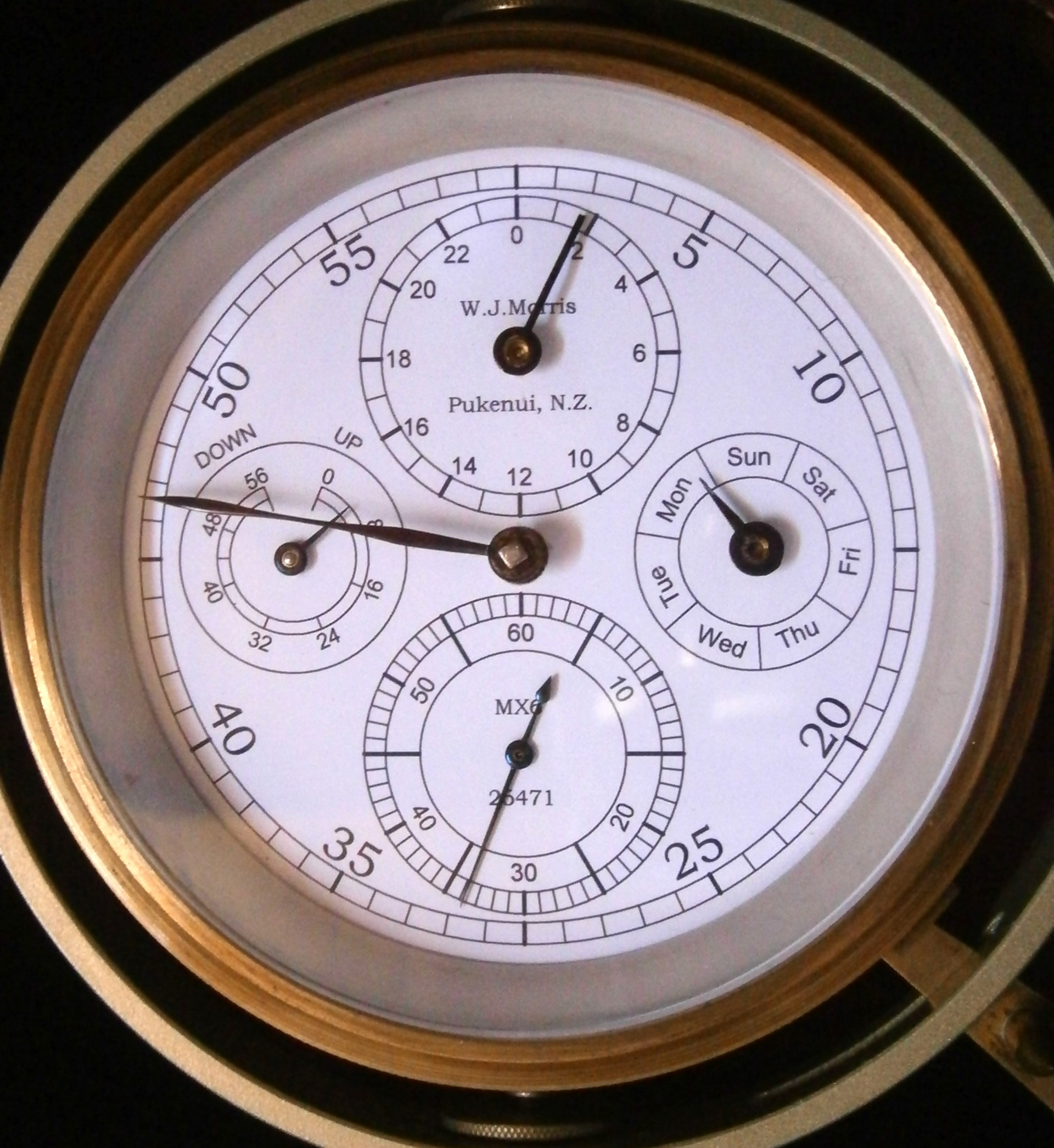
Until recently, I was unaware that the Soviet MX6 chronometer, based on the German war-time Einheitschronometer, had also been made in a four orbit version. However, last October I received an e-mail from someone in Queensland, Australia, together with a photograph of his MX6 4 orbit chronometer (Figure 2).

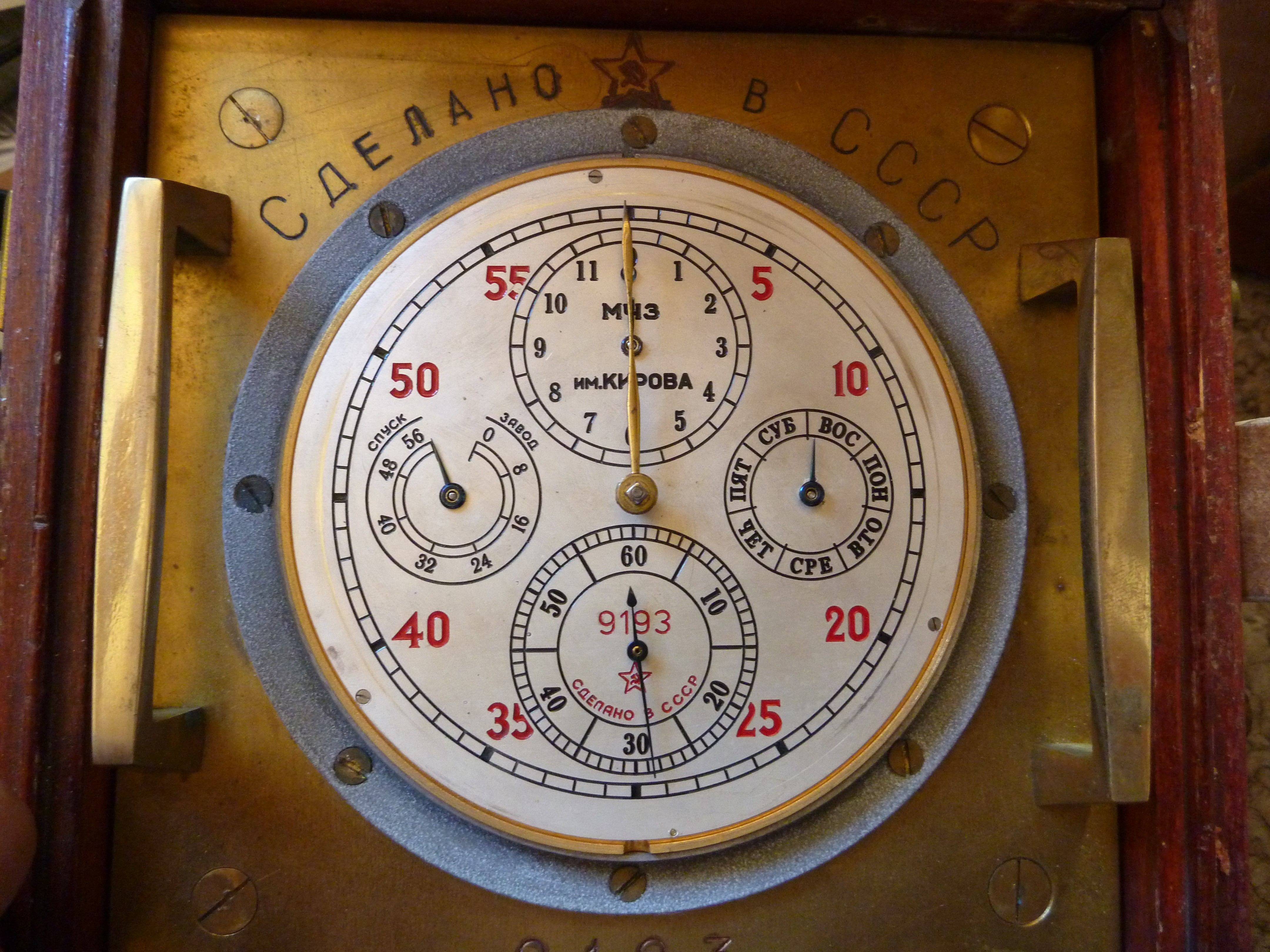
Figure 2: MX6 four orbit chronometer face (courtesy of Tony Manton).
The power reserve dial has moved from 12 to 9 o’clock to make room for the hours dial, and a new one has appeared at 3 o’clock for the days of the week. The Australian friend put me in touch with an owner in the USA and while I was waiting for him to respond, a friend in Korea made contact with the Moscow Watch Factory where these chronometers were made to ask whether any of the old workers could shed light on them. It turned out that only a few, experimental ones had been made, but there had been little interest shown in them and no more were produced.
Then Tim Schultz, an owner in the USA was kind enough to send me some photographs of his instrument. Figure 3 shows the face of what appears to be a surveying chronometer with a rubber suspension. German chronometers with a similar suspension were made during WW II. The words at the top say simply ” Made in the USSR”.
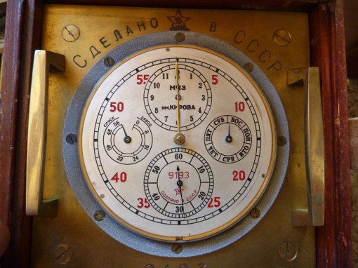
Figure 3: Surveying chronometer (Courtesy of Tim Schultz).
Figure 4 shows the motion work, from which it is possible to deduce at least some of the tooth counts of the pinions and wheels.
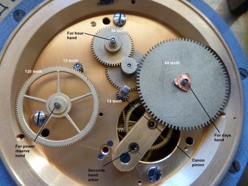
Figure 4: Motion work of MX6 four orbit chronometer (Tim Schultz)
The power reserve modification is simple enough: the 120 tooth wheel has simply been moved to the 9 o’clock position and remains engaged with the 12 tooth pinion that fits on the end of the fusee arbor. It is not possible to count the pinion teeth beneath the hour wheel, but the reductions between the canon pinion and the hour wheel must of course be two factors of 24. The hour wheel appears to drive a pinion immediately beneath a one-tooth pinion that rotates free on its arbor and this latter pinion drives the 84 tooth wheel that carries the days hand. The ratio between the hour wheel and the days wheel must of course be 7 to 1.
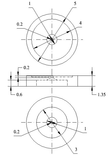
At about this time, I acquired a damaged MX6 chronometer for about half of the usual price, and as I was waiting for it to arrive I thought that if I could get it going, I might make it into a four orbit instrument. Accordingly, I mused over possible designs, aided by an aging CAD program to get the approximate placing of wheel and pinions, to see whether my design might work. Figure 5 shows the final result of my musings.
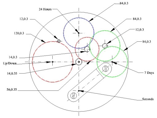
Figure 5: Planned motion work.
The first numbers in the figure are the numbers of teeth in the wheels and pinions and the second number is the Metric module of the teeth.This latter is the diameter in millimetres of the pitch circle of the gear, divided by the number of teeth and is a measure of the tooth size. The pitch circles are shown as dotted lines. The outside diameter is the number of teeth-plus-two divided by the module and is shown as full lines. To avoid having to make a new canon pinion, I kept the old minute wheel too, shown in red at about 2 o’clock, but planned a new pinion for it, so that all the other wheels and pinions could be of 0.3 module rather than the somewhat larger 0.35 module of the canon pinion and minute wheel. This would allow me to fit in all the gears without having to excavate into the foundation ring as in the instrument shown in Figure 4 above. The pinion on the old minute wheel would drive both the new hour wheel and the gear cluster that drives the days wheel. I elected simply to move the power reserve wheel to 9 o’clock. I retained the pivot of the old reserve power wheel for the new hours wheel.
There are various ways to cut the teeth of gears (or more accurately, the space between them). Traditionally, the jobbing clock maker would cut the tooth spaces one by one, using some sort of dividing attachment and the teeth would be of cycloidal form, which can be seen by enlarging Figure 4 by clicking on it. While all the wheels teeth can be cut to correct form with one cutter, the pinions require one cutter for each pinion tooth count up to 8 and in steps of two up to 16 teeth, and these little cutters are astonishingly expensive, with a current unit price of £84, about US$ 104. However, if the teeth are cut by a generating process called hobbing, about which more below, one cutter will cut any number of teeth at a cost of US$ 30, so this is the method that I chose. The tooth form would be involute, which is much more tolerant of errors of spacing of meshing gears. There seems to be a belief among some clock makers that involute gears do not run well when the wheel is driving the pinion, but this is not my experience and the two clocks I have made with involute teeth seem to run exceptionally freely. In any case, in the new motion work the pinions will be driving the wheels.
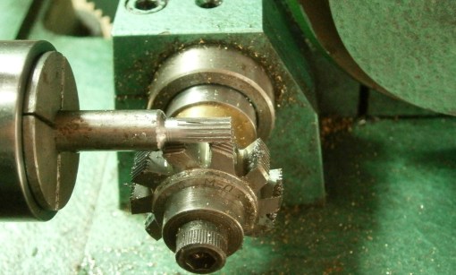
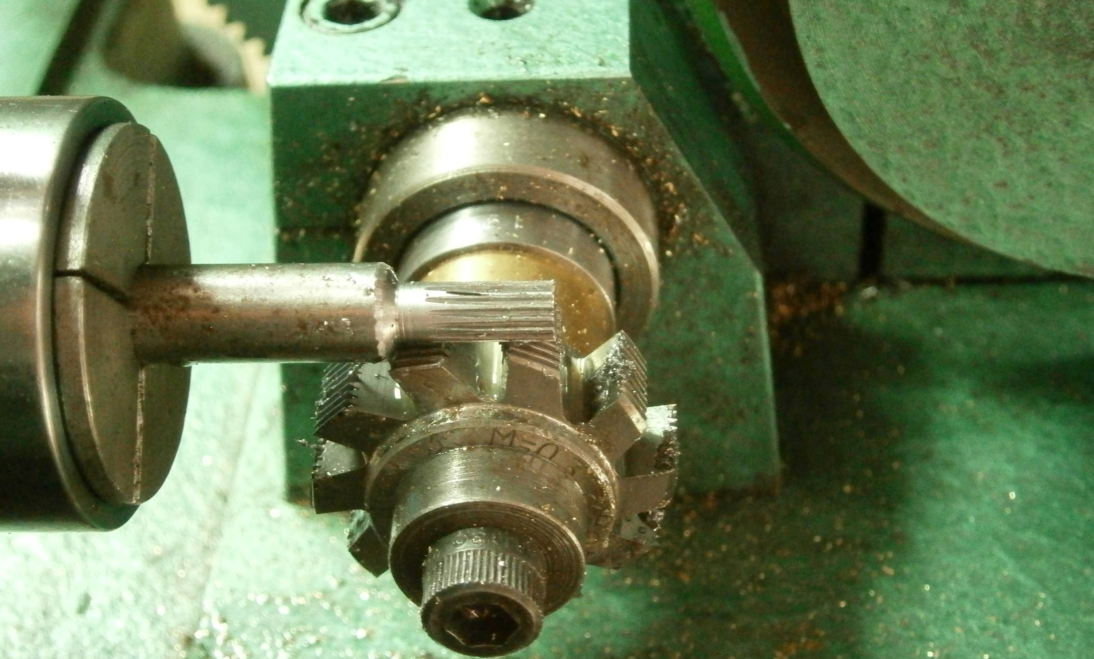
Figure 6: Hobbing a 14 tooth pinion.
The hobbing cutter seen in Figure 6 is essentially a screw thread with straight sides and flat top with cutting teeth formed in it. The spindle carrying it is geared to the spindle carrying the gear blank in such a way that for each revolution of the cutter the blank rotates through one tooth space, in the process generating a tooth with curved sides of involute form. The blank is advanced gradually into the cutter until a gear of the required length has been generated. In the figure. a pinion of 12 teeth has just been completed. Figure 7 shows the 84 tooth wheels being hobbed as a batch.
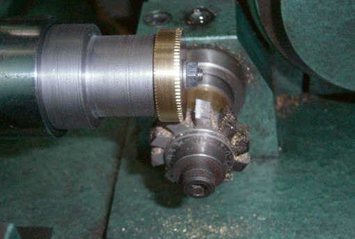
Figure 7: Hobbing a batch of 84 tooth wheels.
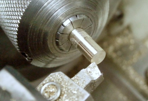
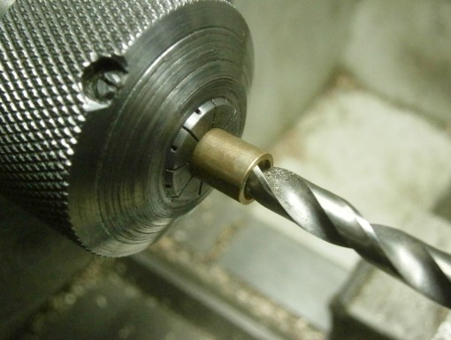
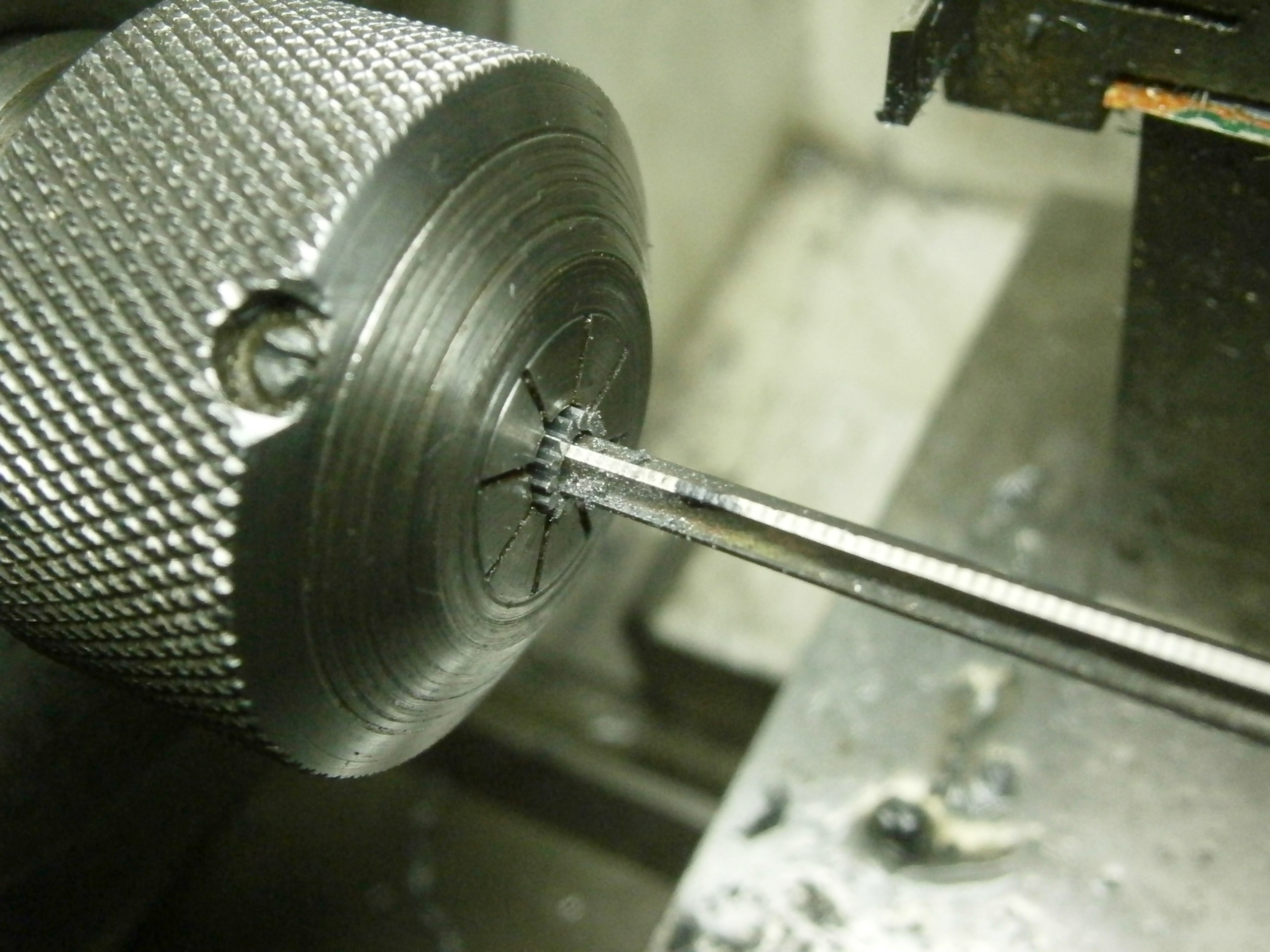
Figure 8 shows a 12 tooth pinion that has been drilled through the centre and is being parted off from the parent metal.
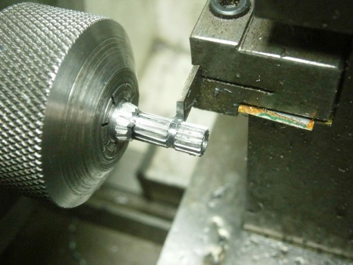
Figure 7: Parting off a pinion.
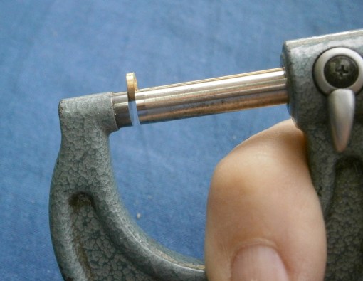
When it came to removing the pivots of the old motion work and re-positioning the power reserve and minute wheels, I discovered that all the pivots were tapered in form, as were the holes in the wheels and pinions, so that the holes in the plates for the pivots and in the hubs of the gears had to be taper reamed to match the standard taper pins I used for the pivots. Figure 8 shows the new pinion for the old hour wheel being reamed.

Figure 8: Reaming a pinion.
Once the wheels and pinions had been turned to size, hobbed, drilled and reamed the wheels were ready to have hubs made and fitted. Once this was done I could start to “plant” them. Before this can be done, the correct centre distance has to be determined and transferred to the pillar plate. The traditional tool is called a depthing tool and though I have made my own it is rather easier for the occasional user to make and use the improvised device shown in Figure 9.
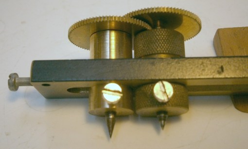
Figure 9:
Two threaded bushes slide in a slot cut into a substantial slab of brass and can be fixed in place by finger nuts. The holes through the centres of the bushes accommodate round rods, one end of which are machined to a running fit in the gears being fitted and the other end of which carries hardened centre points for locating in a hole or scribing.The central rods can be adjusted in height and locked in position too. The gears are placed on the device and the centre distances adjusted until they run sweetly together, at which point the bushes are locked in place.

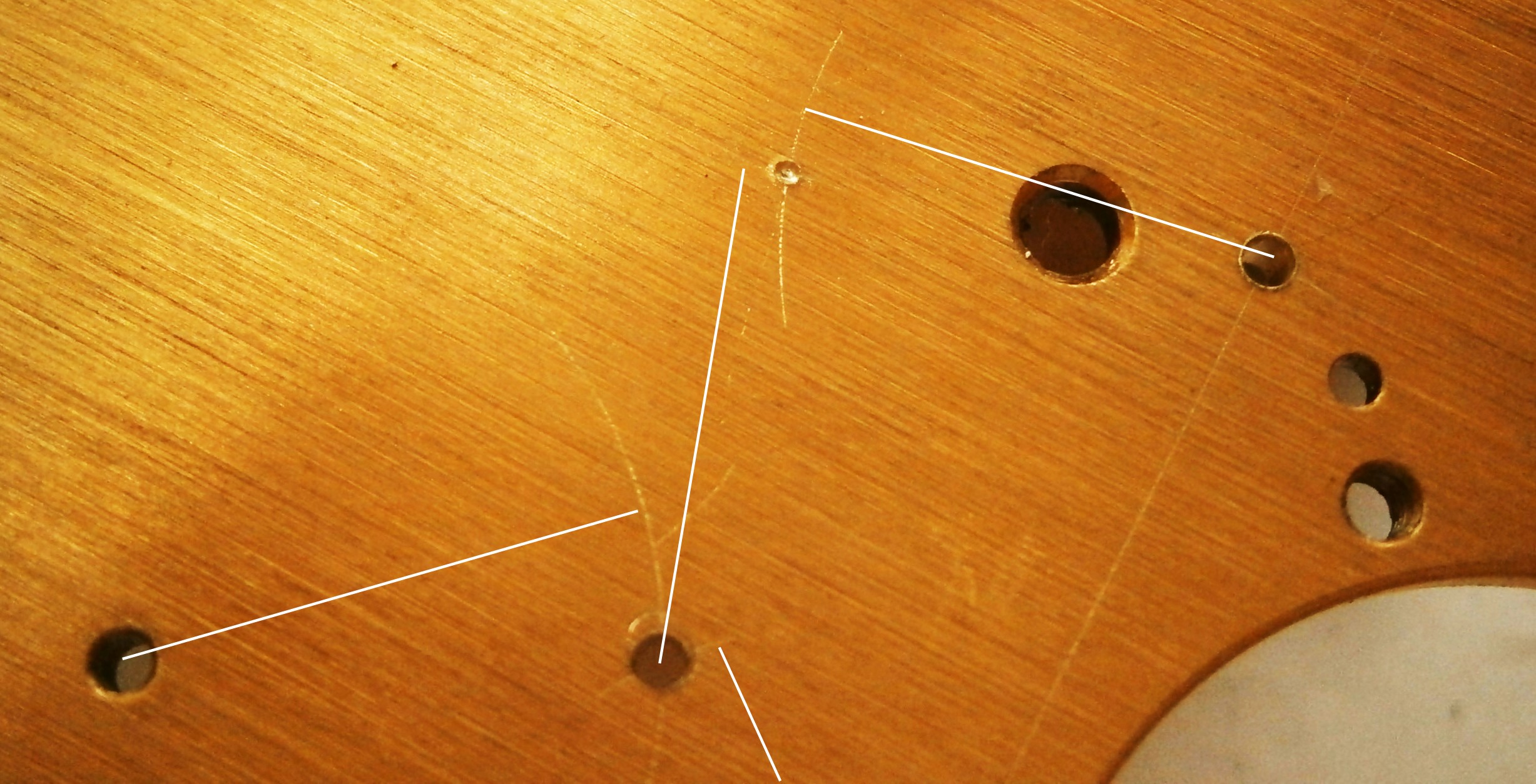
Figure 10: Marking for centres.
In Figure 10, in the upper right of the picture, one arc has been scribed from the hole for the days pivot and another from the hole for the centre wheel pivot, though the latter is not clearly visible in the photo. At the intersection a sharp fine prick punch is used to make a shallow mark at the intersection, and its position is checked and coaxed to the exact position if necessary. The shallow mark is deepened and then a 90 degree punch mark made to guide the drill point. In the lower centre of the photo one centre has been set in the hole for the centre wheel arbor and the other has scribed an arc for the new minute wheel. The latter has then been meshed with the hour wheel and an arc scribed, centred on the hour wheel hole. At the intersection of the arcs at lower centre, the hole for the pivot has been punched, drilled and reamed to size.
Once the holes were drilled, it was a simple matter to insert taper pins and tap (not hammer) them into place. Then I turned and drilled the hubs for the wheels and pinions in brass and fitted them in pairs to check for smooth running. I needed to taper ream the holes in the hub until each gear or gear cluster sat on the pillar plate and ran smoothly on its own before checking that it ran with its partner. I could then mark the taper pins for height, tap them out, cut and smooth off the ends and replace them in their individual holes (there are small manufacturing variations betweeen taper pins). For the days wheel to fit, I had to mill away a couple of millimetres from the diagonal bar that carries the jewels for the third and fourth wheels and I also had to turn a groove in the underside of the days wheel as it otherwise fouled the end of the spring barrel pivot. I could of course have turned off the end of the barrel pivot, but turning the brass of the wheel seemed to be an easier task than removing the tough barrel arbor and grinding off the end. It was also necessary to reduce some of the hubs in length so that the wheels did not interfere with each other or with the underside of the face.
Figure 11 shows the wheels finally fitted in place, pretty well as I had planned it in Figure 5 This left the face to do.
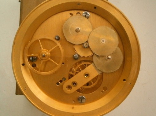
Figure 11: Plan view of new motion work.
It is important that all the holes are in the right place. The hours, minutes and seconds dials retain their previous centres, so I jig drilled these, the three fixing screws and the tiny hole for the locating pin at about 25 minutes past the hour by clamping the old face to a new disc of 1 mm thick brass and using the old holes as a drill guide for the new. When planning the positions of the reserve power and days wheels, I used my makeshift depthing tool to set out the distance between the centre and power reserve holes in the pillar plate and used the same setting from the centre wheel to the days wheel. I could then mark out their positions on the brass disc. I also carefully measured this distance and transferred it to the drawing of the face.
Computer aided draughting makes drawing clock faces relatively easy (Figure 12). I printed the design on to high quality paper and rested it face down on a sheet of glass lit brightly from below. That way, I could bring the glue-coated brass back exactly into coincidence by lining up the holes with the hole markings on the other side of the paper. Once the glue had dried, the smaller holes could be opened up by poking through with a tapered scriber and the excess paper around the hole was cut off against the sharp edge of the backing by rotating the scriber. I cut out the large centre hole with a fine-pointed knife blade. A brushing with PVA glue as a size finished the face.

Figure 12: Face ready to fit.
With a wide range of fonts available, it was tempting to simply make a copy of the MX6 face, except that the days of the week run anti-clockwise in my design, thereby avoiding some complication. I also felt that copying the MX6 might be construed as forgery, and anyway, I think my face looks more elegant without the red numerals. I did however make a concession to colour when it came to the hands and fitted a red hand for the hours to give it some emphasis. Figure 13 shows the final result, with the hands just loosely in place, as, with all the handling the movement has received, I feel a full overhaul would be wise before putting the chronometer into use. I changed my mind about the red hour hand and there seemed to be little point in retaining a gold-coloured minutes hand so I have blacked it in the final version..

Figure 13: Face fitted.
If you have enjoyed reading this post, you will probably enjoy reading my “The Mariner’s Chronometer”, available through http://www.amazon.com and its worldwide branches.
Update 31 January 2017: A more careful tooth count in Figure 4 shows that the canon pinion has 14 teeth and the hour wheel 54 teeth, not 12 and 56 respectively. I have made the appropriate changes to the figure.
Update February 6 2017: Sharp eyed readers will have noticed that in Figure 12, the “Up” and “Down” are incorrectly placed. This has been corrected in Figure 13, which shows the final, final version.
Update February 22 2017: After overhaul daily rate is now + 0.22 seconds per day and mean deviation from the mean over ten days is 0.39 seconds.
.


Recent Comments