29: More on Tipsy Keys

3 01 2018

A note on finding your way around this site: If you know what you are looking for, you can enter a search term in the search box. You can also look in the “List of Posts” to get a date and either click on that date or enter a search term.

In my post Number 8 of July 30, 2013, I wrote about how to make one form of tipsy key. Recently, to amuse myself, I have bought shipwrecked chronometers and tried to bring them back to life. Currently, I am working on a Hamilton Model 21 chronometer which seems to have been dropped, probably while out of its bowl, as all the pivots of the balance and escape wheels are broken and the track on the fusee for the chain has been damaged. Two of the hole jewels of the escapement are also badly chipped and the locking jewel has been broken. While waiting for replacement jewels, I have occupied some time by cleaning the rest of the chronometer and making a new key for it. Since a lot of time is spent setting up for machining parts, it is sometimes almost as quick to make two parts as to make one and this is what I did.

0 Two keys

Figure 1: Key fashions.

Figure 1 shows two tipsy keys that use clutches to prevent winding a chronometer clockwise. The one on the left is from an antique Mercer chronometer that perished when the Australian city of Darwin was largely destroyed by Typhoon Tracy in 1974 and the one on the right is from a German Einheits-Chronometer of 1943. The latter still keeps an excellent rate.

Figure 2 is a composite drawing of the interior mechanism of the second key, while subsequent drawings of the separate parts give the dimensions of the parts as I made them. I had to alter some of the dimensions of the knob so as to use what I had available in the way of brass stock, but as long as the square hole fits the winding square of the chronmeter, the dimensions do not have to be identical to the original.

Tipsy key composite drwg
Figure 2: The interior of the key.

The clutch teeth on the end of the winding shaft inside the conical body are held in engagement with the teeth on the knob by means of a short helical spring. The teeth are sloped so as to slip if the knob is turned clockwise but to engage if turned anti-clockwise.

It is a simple turning exercise to make the shaft (Figure 3), by turning down a piece of 8 mm stock to 6 mm, drilling the end to a depth of about 25 mm to a diameter equal to the across-flats dimension of the chronometer winding square, and parting off.

Tipsy key shaft drwg

Figure 3: Drawing of shaft.

The round hole then serves as a guide to convert the round hole into a square one, while the depth of the hole allows a square needle file to get a decent grip on the metal. The nearly completed filing is shown in Figure 4. Of course, those lucky people who possess small broaches could use them and it is also possible to drill square holes with an appropriate attachment to the drilling machine.

New key 003

Figure 4: Converting a round hole to a square one.

Tipsy key body drwg

Figure 5: Body drawing.

For the body, I turned down a piece of 20 mm round brass bar to 18 mm, drilled and reamed the centre hole to 6 mm and followed the 6 mm hole with an 8 mm slot drill to form a flat-bottomed hole as shown in Figure 6. As I was making two keys, for each tool set up I switched ends of a length of bar.

2 Counterbore 8

Figure 6: 8 mm hole counter-bored.

The top slide is then set over to 12.5 degrees and the conical outside generated (Figure 7), before parting off to length. Technically, I suppose the shape should be described as a frustrum of a cone.

2.1 Body turn

Figure 7: Generating conical shape.

I postponed drilling and tapping the M3 (or 6 BA would do) holes until the knob was made. Thirty millimetre  stock would have been better than the 26 mm I used, as it would have given me a key with a bit more leverage.

Knob drrwg

Figure 8: Knob drawing.


2.2 Knob turn

Figure 9: Turning diameters of knob.

Making the knob begins by turning  the 8 and 20 mm diameters shown in Figure 8. The bar is then set up in a vice on the milling machine to form the flat parts of the knob (Figure 10). This is perhaps a good spot to point out that tools for cutting brass need to be sharp and preferably reserved for use only on brass, as once they have been used on steel they tend to skid over brass.

3 Mill flat 1

Figure 10: Milling flats.

The second flat is formed  by rotating the bar through 180 degrees and checking with a micrometer that the surfaces are parallel before making the final cut on the second surface. While it was still attached to the bar, I used a simple template to mark out the complex shape (Figure 11), before cutting around it using a piercing saw. No doubt it could be machined using some sort of computer-aided process, but with a little practice and a sharp saw blade it is much quicker to cut it by hand and finish off with sharp files.


4 Template

Figure 11: Using template to mark out for sawing to shape.

This is perhaps a good moment to drill holes at tapping size for the screws in the knob. They will be used to spot the holes in the body and then enlarged to a clearance size later.

Next comes the machining of the clutch teeth, and it needs some thought and care to make sure that they slope in the correct direction! The knob can be held by the flats in a machine vice that tilts. I guessed that the teeth tilted at 30 degrees, but 25 degrees would have given more clearance for the side of the 3 mm diameter end mill at the end of its cut (Figure 12).

5 Mill knob tooth

Figure 12: Clutch tooth being formed.

The same set-up is used for the teeth on the end of the shaft, as shown in Figure 13.

6 Mill shaft tooth

Figure 13: Milling teeth on shaft.

After cleaning off burrs with a fine file, the key can now have a trial assembly and a spring cut to length so that the teeth are held in engagement and that there is enough free space for them to slip when turned clockwise.

Drilling for the tapping holes in the body presents minor problems, as its shape prevents it from being held in a vice. I got around this by assembling the key, holding the shaft in a drilling vice and rotating the body until the teeth were locked, then drilling the hole to full length. Though brass is traditionally cut dry, it is a sound plan to use a little lubricant when tapping the holes, as there is a tendency to jamming unless the taps are sharp. Most of us cannot afford to keep two sets of taps, one for sole use on brass, so a little lubricant may save a lot of heart ache due to a work piece having to be scrapped because a broken tap is jammed in it.

A little grease and assembly with a couple of countersink-head screws completes the key (Figure 14).

Compendium

Figure 14: Two new and two old.


I hope this account was of interest to you. You will find much more about marine chronometers in my book. Take a look at “About the Mariner’s Chronometer”.


Advertisement


28: A tale of woe that ended well.

24 11 2017

Apart from Soviet era MX6 chronometers other chronometers are out of my financial reach, unless I buy damaged ones “for parts or repair”. As I now have several MX6 s I can only justify buying another if I challenge myself to right the wrongs it may have suffered. At the beginning of October I returned from the USA with a homeless MX6, of which the seller had said it would not wind beyond 48 hours, whereas 56 hours is the norm. The Department of Homeland Security had rummaged through my baggage, presumably upon seeing with X-rays a dense circular object  with clockwork, and had replaced the layers of bubble wrap after a fashion, so further damage had not occurred.

Once recovered from a 15 hour flight from Houston to New Zealand, followed by a 5 hours drive to my home in the Far North, I set about exploring the innards of the instrument. The end of the chain around the barrel was at the back and  the clock ran when started, so, rather incautiously, I wound the clock to 48 hours and continued, forgetting that the stop-work needs a full wind to operate. There came a loud snapping noise followed by a frenzied whirring…Upon opening the machine I of course found that the barrel end of the chain was no longer attached to the barrel, but of a hook there was no sign (Figure 1 – click on the photo to enlarge and use back arrow to return to text)). The barrel arbor had cast off its ratchet, so happily the whirring had come from the barrel rather than from the movement.

Broken chain labelled

Figure 1: Broken and short chain.

Note how the chain, even if it had had a hook, is still one turn of the fusee short of reaching the stop bar. It seems that someone, not necessarily the seller, had simply stuffed the broken end of the chain  into the barrel slot. In any event, when the chain lost contact with the barrel, either the free end or the recoil of the movement had done a lot of damage. The moral of the story is that you should not wind an obviously defective chronometer to see whether it goes. It should have been obvious to me that a bit of the chain was missing and that the stop work would not operate, risking breakage of the chain at the end of winding if it had a hook into the barrel or, as I found out, the chain simply let go of the barrel. The chain was about 120 mm short of the required length of 850 mm and I replaced it with steel cable as described in post number 27 of 13th February, 2017.

Once fully dismantled, I found that the upper pivot of the escape wheel had been repaired by the classical method of drilling down the broken end and letting in a new pivot. The new pivot was rather short and it had not needed much to knock it out of place. I had a spare escape wheel arbor and pinion which had a broken upper pivot and I used my preferred method of repair, by using a muff, as described in post number 7 of 22nd July, 2013. Using the classical method, if the tiny drill, around 0.6 mm in diameter, breaks off in the broken arbor, you may not be able to get the broken stub out of the hole and, it being made of high speed steel, you won’t be able to drill it out.

That was the easy bit. The detent spring, which must have been intact when I first tried it, because the clock ran, had taken on a Z-shape. At least it was not broken, and the fact that it had distorted without breaking gave me some hope that I might be able to straighten it. While is was possible to straighten a passing spring by drawing it between my finger nails (see post 22 0f 20th June 2016), the detent spring is made of sterner stuff and so I used a pair of pliers with circular jaws, bending the spring while drawing it between the jaws, as shown in Figure 1, which is posed with a slip of brass shim between the jaws.

Straighten spring 001

Figure 2: Technique to straighten spring.

Drawing the spring between the jaws, while angling the pliers against the bend, irons out any kink, so that a reverse bend is not simply added to the original bend. Eventually I managed to get the spring straight again without breaking it.

The next step was to replace the passing spring. While some chronometers had oval holes in the passing spring to allow for some adjustment, in the MX6, there is no provision for this and the tip of the passing spring projects rather less than a millimeter beyond the tip of the horn. This means that in adjusting the depth of the detent, this is the total range of available movement and in lifting the passing spring the discharging jewel must pass clear of the tip of the detent. On the return, the jewel must lift the locking stone off a tooth of the escape wheel far enough to unlock the wheel. If the locking stone is too deep in the escape wheel teeth, unlocking won’t happen, so some adjustment of the banking screw (or stop button in the Hamilton M21 escapement) may be necessary. It seems to be about right when a tooth of the escape wheel overlaps about one third of the width of the jewel face.

In making these interdependent adjustments, I start with the locking stone and check that every tooth of the escape wheel is locked by this amount, just in case the upper pivot is bent or for some reason there has been uneven tooth wear. Once I have done this, I then start with the tip of the detent well clear of the discharging jewel and move it in very gradually, operating the escape wheel with a finger until the passing spring is lifted off the horn of the detent. Only then do I check that unlocking takes place on the return stroke. If the depth of the detent is set too deep, the discharging jewel will strike the back of the horn on the return, instead of the passing spring, and refuse to go further because the banking screw stops it, a very good reason for checking the operation of the escapement by hand, rather than under power, which would risk breaking the discharging jewel or a balance wheel pivot.

Then one can wind the chronometer a turn or so and let it run under power, being prepared to stop it at the first sign of tripping, which is usually cured by increasing the depth by a tiny amount each time. This of course assumes that you have not disturbed the mutual angles between the upper balance wheel spring stud, the discharging roller and the impulse roller, another interdependent set of adjustments. I knew that I had all the angles correct and it needed less than an eighth of a turn of the depth-adjusting screw to cure occasional tripping.

Despite all its trials, the chronometer responded to my ministrations and ran sweetly on a full wind. After some adjustment, it ran over 20 days with a mean gaining error at room temperature of 0.9 seconds per day, with the mean of the deviations from this mean error being 1.03 seconds. Making a case for it took a little while, but it seems happy enough in what I was able to achieve (Figures 3 and 4).

Case 3 4ths view

Figure 3: Exterior of new case.

I was able to use some Hamilton handles, but the gimbals lock and the brass corners I had to make myself.

Case open from L

Figure 4: Chronometer in new home.


27: Fusee chain substitute

13 02 2017

A few weeks ago I received a chronometer which seems to have been heavily damaged by dropping, possibly while out of its bowl . The upper balance pivot was broken, the upper jewel of the third wheel was absent, or rather, it was present in many tiny pieces, and there were burrs raised on a few adjacent teeth of the great wheel. The stop bar of the stop work was stuck and the maintaining power did not work. The hands were absent and so was the fusee chain.

I have covered re-pivoting in posts 6 and 7 and making hole stones in post 26, though when there is no end stone to take into account, the process of making one is a rather simple turning operation. A little careful filing removed the burrs on the great wheel. Dismantling the stop work and maintaining power revealed dried-up grease, so that merely cleaning the parts of all old lubricant and replacing it with new brought these back to life. That left the hands to make and the chain to replace. I will cover making hands in a later post.

To a mariner, “cable” used to mean “A large rope by means of which the Ship is secured to the Anchor.” When it became possible in the nineteenth century to make large chains economically, they began to talk of “chain cable”. While the weight lines in clocks were of gut, this presumably was not strong enough to use as the link between spring barrel and fusee, so chain was used. It may well be that the technology of the eighteenth century was not equal to making wire lines that were both flexible and strong, and since chronometer makers were nothing if not conservative, the use of chain continued to the end of chronometer manufacture. These chains, which look rather like miniature cycle chains, were made by specialists and the chronometer repairer limited himself to repairing a broken link, usually by simply removing it.

Such books as there are that tell of chronometer repair are silent on what to do when the chain is completely absent. I found that I could buy a replacement chain for a trifling US$190, but as readers will perhaps by now have gathered, I am no spendthrift, and I began looking for an alternative to chain. The problem resolved itself into several requirements. The replacement has to be strong enough for its task; it has to be flexible enough; and it has to be possible to attach it to the barrel and fusee without special techniques. It also has to fit in the pre-existing groove of the fusee. These groves are always flat-bottomed so that conversion to a round cable is possible.

Less than a kilometre from my house is a famous game fishing club from which tormenters of large fish set sail. It is considered unsporting of the fish to bite through the trace of the hook and so it is often nowadays made of steel wire. A visit to a local supplier of fishing tackle provided me with a metre of stainless steel wire 0.8 mm in diameter for the sum of NZ$1.20 and I thought my problems were at least partly solved.

I carved hooks out of some scrap roofing iron using a piercing saw and files, and immediately encountered some problems: I could not solder the wire to the hooks, it was not flexible enough to allow me to pass it through a hole and bind it back on itself and when I made a little brass bush and squeezed it on to the end of the wire, it projected enough to foul either the top plate or the ratchet wheel of the maintaining power or the centre wheel arbor. By creative bodging I managed to overcome this, only to find that the wire was almost too stiff to be able to fit it. I then recalled that many years ago a kind person had given me a box of bits and pieces that he had bought at a deceased clock maker’s clearance auction with no clear idea what to do with them. Among the bits and pieces were several pieces of flexible wire and one length of the correct diameter to fit between the cheeks of the fusee groove. It appeared to be of multi-stranded steel, was very flexible; and it could be doubled back on itself with relative ease.

A test of its solderability revealed that it was plastic-coated and when I burned off the coating and scraped the wire clean, its fine structure could be revealed and contrasted with the relatively coarse structure of the stainless steel trace wire ( middle, Figure 1). The figure also shows how I at first anchored the trace wire to a hook with a bush.

ends-001

Figure 1: Stainless steel trace (left and centre) and multi-stranded flexible steel (right)

Attaching the cable to the barrel with a normal-shaped hook was relatively easy, using techniques well known to a mariner setting up standing rigging. In my case, after doubling back the wire on itself I held the bight in a small vice while binding it with some fine nichrome wire that I had bought for another purpose. As Figure 2 shows, the free end  just clears the top plate.

attach-to-barrel

Figure 2: Attachment of cable to the barrel hook.

Attaching the other end to the fusee hook required some modification to the normal shape of the hook, as otherwise the standing end of the wire would not lead into the beginning of the fusee groove. Thus, I made the hook deeper than usual so that the end of the hook could be twisted through 90 degrees and bring the cable in line with the fusee groove (Figure 3).

attach-to-fusee-1

Figure 3: Attachment of cable to modified fusee hook.

I have not been able to find a supply of similar wire. Phosphor bronze wire 1.5 mm in diameter is available but is too big. I tried unravelling  a sample of the wire and using only three of the five strands, but it stubbornly refused to be pulled straight. As it was hard drawn, I tried annealing it in a gas flame while pulling on it, but it broke under a very moderate stress. Clock fusee chain is too wide and pocket watch chain is too short.so I am very glad to have been able to find just the right diameter.

After a thorough overhaul and repair, the chronometer sprang into life with a very strong balance motion. I have gradually regulated it  over three days and it is currently losing at the rate of 1.3 seconds a day. I hope that with a little more tweaking it will do a little better.

If any reader knows where to obtain flexible, multi-stranded steel or phosphor-bronze wire of between 0.8 and 1.0 mm in diameter, I would be glad to hear of it.


26: Making a hole stone.

24 01 2017

When chronometers get dropped sometimes it is not only the pivots that suffer. The jewels, often known as “stones,”  sometimes get chipped or cracked. Continuing to run a chronometer with a cracked stone is to invite the pivot to develop grooves and eventually the pivot gives way. A half-dead pivot can be seen at Figure 2 of post number 5 of April 2013. When a stone is chipped and the hole in it becomes irregular, often the chronometer will not run at all, or if it does, may have an irregular rate, or only run one way up. Unfortunately, replacement hole stones in chronometer size are hard to come by for the occasional repairer, though occasionally mounted stones turn up for Soviet chronometers on e-bay – at a price.

Early chronometers had few jewels, but ran well with the pivots running in the brass of the plates, or in bushes let into the plates. A few days ago, I became impatient waiting for a replacement to arrive and thought to make a replacement out of brass. Phosphor-bronze might have been better, but I didn’t have any. The main problem is in drilling the tiny hole required, 0.2mm diameter for the hole stones of the Soviet MX6 chronometer’s balance and escape wheel staffs. It is now possible to buy tungsten carbide drills of this size, but they were intended for drilling fibreglass printed circuit boards using specialised machinery. In the amateur or repairer’s workshop, where the tailstock of the lathe or the drill chuck may not be perfectly co-axial with the lathe axis, drilling a tiny hole off centre results in the drill wobbling and then breaking. In what follows, I have tried to show a method that works for me in producing emergency replacement hole stones, but first, a sketch of an MX6 holes stone. I have not dimensioned it fully, as other makes of chronometers may well need different thicknesses and diameters.

hole-stone

Figure 1: Sketch of MX6 chronometer hole stone.

The upper face of the stone has an annulus  excavated for a depth of about 0.3 mm around a central island and the face of the island is relieved by a “whisker”, perhaps 0.05 mm, so that when the end stone is in place, there is a slight gap between them to allow oil to run by capillary action and form a reservoir. The lower face is also relieved by drilling in stages so as to leave a hole 0.20 mm in diameter and of about the same length. The point of a larger drill leaves a conical lead-in to the hole, to help the end of the pivot to find its way and then an end mill gives a flat-bottomed hole surrounding. it.

5-face-blank

Figure 2: Facing end of the blank.

A scrap piece of brass is first turned down to a close fit in the hole in the plate, in this case 5.00 mm diameter and then carefully faced (Figure 2)

2-excavate-end

Figure 3: Excavating annulus.

Then the annulus is turned away with a round-nosed tool (Figure 3). Note that the tool has negative rake, which gives a very fine finish on brass. It doesn’t matter how deep the excavation is, as long as it is much more than a whisker deep! Then the face of the island is relieved by 0.05 mm, as noted above and the blank parted off  a little over-thick (Figure 4).

3-part-off

Figure 4: Parting off.

One must now digress to make a shallow socket in the end of a scrap of brass bar (Figure 5).

4-make-spcket

Figure 5: Drilling a socket

The diameter of the scrap doesn’t matter as long as it is larger than that of the blank, but the size and the depth of the hole does matter. Unless a drill is perfectly sharpened it is likely to drill over-size, so I suggest making a start with a centre drill, followed in this case by a 4.7 mm drill. Then even a 5 mm drill that has slightly un-equal cutting lips will follow the hole so-formed and be of the correct size. The finish of the walls may not be great, but the size will be right. I made mine a mere 1 mm deep. Before proceeding further, measure the thickness of the blank so as to know how much to take off the thickness. As the faces of parted-off material may slightly concave or convex, measure near the edge, as in Figure 6.

measure-003

Figure 6: Measuring thickness of the blank.

Then the socket is heated gently and annointed with flake shellac to leave an even coating inside. While the shellac is still liquid, the blank is firmly seated in the socket and the whole allowed to cool, when the socket and blank can be replaced in the lathe.

1-face-end

Figure 7: Facing underside of blank.

After careful facing and removing metal to the correct thickness (Figure 7), drilling can begin. Here, careful depth control is essential, using the graduated thimble on the tail stock quill rather than a ruler. A dial gauge could also be pressed into service. Carbide drills are usually sharpened by the four facet method so that they are self-centring, but to make sure, make a dimple with the much more rigid centre drill and then feed in the 1 mm drill carefully to a pre-calculated depth (Figure 8).

6-drill-1-mm

Figure 8: Drilling with 1 mm carbide drill.

In the example shown, this leaves only 0.2 mm for the very slender 0.20 mm drill to tackle and there should be no problem of it wandering off centre , since the larger drill leaves a conical lead in.(Figure 9).

7-drill-0-2-mm

Figure 9: Drilling with 0,20 mm carbide drill.

Although tungsten carbide is a very strong and dense material it is also brittle, so the lathe has to run at high speed and the feed has to be slow to avoid breakages. Once the hole has been drilled successfully, it remains only to use a 3 or 4 mm end mill to form the relieving step. The depth of this must also be calculated, as it is important to leave the conical run-in area to guide the pivot into the 0.20 mm hole. The new stone is now separated from the socket by heating and given a soak in alcohol to remove all traces of shellac, after which the thickness can be checked. It is a good idea to brush the floor around the bench when separating the stone, to make it easier to find it when you drop it on the floor.

Figure 10 is a composite photograph to show both sides.

OLYMPUS DIGITAL CAMERA

Figure 10: The finished stone.

I don’t know how long this improvised lower hole stone for a chronometer escape wheel pivot will last, but at the moment, the instrument is running well and heading for a good rate. I have a French drum clock that was one of  my grandmother’s wedding present in which the relatively fine pivots run directly in the plates and there is no sign of wear at the low power end of the train after over a hundred years of continuous running, so I hope that my stones will also last over a hundred years. If they do not, they are easy to replace.


25:Making a Four Orbit Face and Motion Work.

22 01 2017

With the exception of Figure 1, all figures may be enlarged by clicking on them. Return to the text by using the back arrow.

I have long been aware that the Hamilton Model 21 chronometer had a version with four orbits, that is to say that as well as the usual minute hand it had four subsidiary dials: the usual seconds and power reserve dials with two extra ones to show 24 hours and the days of the week, shown in Figure 1 (I have been unable to trace the source of this photo). The movement of the chronometer is the same as standard, but the motion work, the system of pinions and wheels behind the face that drives the hands, is different. Only 27 were made and were designated Model 221. One sold in 1982 for $6,600, underlining its rarity.

hamilton-21

Figure 1: Hamilton Mod. 21 four orbit face.

When navigating in the vicinity of the International Date Line it is surprisingly easy to take out data from the Nautical Almanac from the wrong day of the week, and on long voyages across the Pacific, when tired, it is also possible to get the Greenwich time wrong by twelve hours. At least, I gather that this was the ostensible reason for making a four orbit version. However, seafarers are a conservative lot and the idea never caught on.

Until recently, I was unaware that the Soviet MX6 chronometer, based on the German war-time Einheitschronometer, had also been made in a four orbit version. However, last October I received an e-mail from someone in Queensland, Australia, together with a photograph of his MX6 4 orbit chronometer (Figure 2).

tony-mantons

Figure 2: MX6 four orbit chronometer face (courtesy of Tony Manton).

The power reserve dial has moved from 12 to 9 o’clock to make room for the hours dial, and a new one has appeared at 3 o’clock for the days of the week. The Australian friend put me in touch with an owner in the USA and while I was waiting for him to respond, a friend in Korea made contact with the Moscow Watch Factory where these chronometers were made to ask whether any of the old workers could shed light on them. It turned out that only a few, experimental ones had been made, but there had been little interest shown in them and no more were produced.

Then Tim Schultz, an owner in the USA was kind enough to send me some photographs of his instrument. Figure 3 shows the face of what appears to be a surveying chronometer with a rubber suspension.  German chronometers with a similar suspension were made during WW II. The words at the top say simply ” Made in the USSR”.

mx6-face-in-box-tim-schultz

Figure 3: Surveying chronometer (Courtesy of Tim Schultz).

Figure 4 shows the motion work, from which it is possible to deduce at least some of the tooth counts of the pinions and wheels.

mx6-motion-work

Figure 4: Motion work of MX6 four orbit chronometer (Tim Schultz)

The power reserve modification is simple enough: the 120 tooth wheel has simply been moved to the 9 o’clock position and remains engaged with the 12 tooth pinion that fits on the end of the fusee arbor. It is not possible to count the pinion teeth beneath the hour wheel, but the reductions between the canon pinion and the hour wheel must of course be two factors of 24. The hour wheel appears to drive a pinion immediately beneath a one-tooth pinion that rotates free on its arbor  and this latter pinion drives the 84 tooth wheel  that carries the days hand. The ratio between the hour wheel and the days wheel must of course be 7 to 1.

At about this time, I acquired a damaged MX6 chronometer for about half of the usual price, and as I was waiting for it to arrive I thought that if I could get it going, I might make it into a four orbit instrument. Accordingly, I mused over possible designs, aided by an aging CAD program to get the approximate placing of wheel and pinions, to see whether my design might work. Figure 5 shows the final result of my musings.

layout

Figure 5: Planned motion work.

The first numbers in the figure are the numbers of teeth in the wheels and pinions and the second number is the Metric module of the teeth.This latter is the diameter in millimetres of the pitch circle of the gear, divided by the number of teeth and is a measure of the tooth size. The pitch circles are shown as dotted lines. The outside diameter is the number of teeth-plus-two divided by the module and is shown as full lines. To avoid having to make a new canon pinion, I kept the old minute wheel too, shown in red at about 2 o’clock, but planned a new pinion for it, so that all the other wheels and pinions could be of 0.3 module rather than the somewhat larger 0.35 module of the canon pinion and minute wheel. This would allow me to fit in all the gears without having to excavate into the foundation ring as in the instrument shown in Figure 4 above. The pinion on the old minute wheel would drive both the new hour wheel and the gear cluster that drives the days wheel. I elected simply to move the power reserve wheel to 9 o’clock. I retained the pivot of the old reserve power wheel for the new hours wheel.

There are various ways to cut the teeth of gears (or more accurately, the space between them). Traditionally, the jobbing clock maker would cut the tooth spaces one by one, using some sort of dividing attachment and the teeth would be of cycloidal form, which can be seen by enlarging Figure 4 by clicking on it. While all the wheels teeth can be cut to correct form with one cutter, the pinions require one cutter for each pinion tooth count up to 8 and in steps of two up to 16 teeth, and these little cutters are astonishingly expensive, with a current unit price of £84, about US$ 104. However, if the teeth are cut by a generating process called hobbing, about which more below, one cutter will cut any number of teeth at a cost of US$ 30, so this is the method that I chose. The tooth form would be involute, which is much more tolerant of errors of spacing of meshing gears. There seems to be a belief among some clock makers that involute gears do not run well when the wheel is driving the pinion, but this is not my experience and the two clocks I have made with involute teeth seem to run exceptionally freely. In any case, in the new motion work the pinions will be driving the wheels.

pinion-hob

Figure 6: Hobbing a 14 tooth pinion.

The hobbing cutter seen in Figure 6 is essentially a screw thread with straight sides and flat top with cutting teeth formed in it. The spindle carrying it is geared to the spindle carrying the gear blank in such a way that for each revolution of the cutter the blank rotates through one tooth space, in the process generating a tooth with curved sides of involute form. The blank is advanced gradually into the cutter until a gear of the required length has been generated. In the figure. a pinion of 12 teeth has just been completed. Figure 7 shows the 84 tooth wheels being hobbed as a batch.

gears-wheel-hob

Figure 7: Hobbing a batch of 84 tooth wheels.

Figure 8 shows a 12 tooth pinion that has been drilled through the centre and is being parted off from the parent metal.

pinion-part

Figure 7: Parting off a pinion.

When it came to removing the pivots of the old motion work and re-positioning the power reserve and minute wheels, I discovered that all the pivots were tapered in form, as were the holes in the wheels and pinions, so that the holes in the plates for the pivots and in the hubs of the gears had to be taper reamed to match the standard taper pins I used for the pivots. Figure 8 shows the new pinion for the old hour wheel being reamed.

pinion-ream

Figure 8: Reaming a pinion.

Once the wheels and pinions had been turned to size, hobbed, drilled and reamed the wheels were ready to have hubs made and fitted. Once this was done I could start to “plant” them. Before this can be done, the correct centre distance has to be determined and transferred to the pillar plate. The traditional tool is called a depthing tool and though I have made my own it is rather easier for the occasional user to make and use the improvised device shown in Figure 9.

planting-2

Figure 9:

Two threaded bushes slide in a slot cut into a substantial slab of brass and can be fixed in place by finger nuts. The holes through the centres of the bushes accommodate round rods, one end of which are machined to a running fit in the gears being fitted and the other end of which carries hardened centre points for locating in a hole or scribing.The central rods can be adjusted in height and locked in position too. The gears are placed on the device and the centre distances adjusted until they run sweetly together, at which point the bushes are locked in place.

punch-mark

Figure 10: Marking for centres.

In Figure 10, in the upper right of the picture, one arc has been scribed from the hole for the days pivot and another from the hole for the centre wheel pivot, though the latter is not clearly visible in the photo. At the intersection a sharp fine prick punch is used to make a shallow mark at the intersection, and its position is checked and coaxed to the exact position if necessary. The shallow mark is deepened and then a 90 degree punch mark made to guide the drill point. In the lower centre of the photo one centre has been set in the hole for the centre wheel arbor and the other has scribed an arc for the new minute wheel. The latter has then been meshed with the hour wheel and an arc scribed, centred on the hour wheel hole. At the intersection of the arcs at lower centre, the hole for the pivot has been punched, drilled and reamed to size.

Once the holes were drilled, it was a simple matter to insert taper pins and tap (not hammer) them into place. Then I turned and drilled the hubs for the wheels  and pinions in brass and fitted them in pairs to check for smooth running. I needed to taper ream the holes in the hub until each gear or gear cluster sat on the pillar plate and ran smoothly on its own before checking that it ran with its partner. I could then mark the taper pins for height, tap them out, cut and smooth off the ends and replace them in their individual holes (there are small manufacturing variations betweeen taper pins). For the days wheel to fit, I had to mill away a couple of millimetres from the diagonal bar that carries the jewels for the third and fourth wheels and I also had to turn a groove in the underside of the days wheel as it otherwise fouled the end of the spring barrel pivot. I could of course have turned off the end of the barrel pivot, but turning the brass of the wheel seemed to be an easier task than removing the tough barrel arbor and grinding off the end. It was also necessary to  reduce some of the hubs in length so that the wheels did not interfere with each other or with the underside of the face.

Figure 11 shows the wheels finally fitted in place, pretty well as I had planned it in Figure 5 This left the face to do.

gears-plan

Figure 11: Plan view of new motion work.

It is important that all the holes are in the right place. The hours, minutes and seconds dials retain their previous centres, so I jig drilled these, the three fixing screws and the tiny hole for the locating pin at about 25 minutes past the hour by clamping the old face to a new disc of 1 mm thick brass and using the old holes as a drill guide for the new.  When planning the positions of the reserve power and days wheels, I used my makeshift depthing tool to set out the distance between the centre and power reserve holes in the pillar plate and used the same setting from the centre wheel to the days wheel. I could then mark out their positions on the brass disc. I also carefully measured this distance and transferred it to the drawing of the face.

Computer aided draughting makes drawing clock faces relatively easy (Figure 12). I printed the design on to high quality paper and rested it face down on a sheet of glass lit brightly from below. That way, I could bring the glue-coated brass back exactly into coincidence by lining up the holes with the hole markings on the other side of the paper. Once the glue had dried, the smaller holes could be opened up by poking through with a tapered scriber and the excess paper around the hole was cut off against the sharp edge of the backing by rotating the scriber. I cut out the large centre hole with a fine-pointed knife blade. A brushing with PVA glue as a size finished the face.

blank-face

Figure 12: Face ready to fit.

With a wide range of fonts available, it was tempting to simply make a copy of the MX6 face, except that the days of the week run anti-clockwise in my design, thereby avoiding some complication. I also felt that copying the MX6 might be construed as forgery, and anyway, I think my face looks more elegant without the red numerals. I did however make a concession to colour when it came to the hands and fitted a red hand for the hours to give it some emphasis. Figure 13 shows the final result, with the hands just loosely in place, as, with all the handling the movement has received, I feel a full overhaul would be wise before putting the chronometer into use. I changed my mind about the red hour hand and there seemed to be little point in retaining a gold-coloured minutes hand so I have blacked it in the final version..

face-corrected-001

Figure 13: Face fitted.

If you have enjoyed reading this post, you will probably enjoy reading my “The Mariner’s Chronometer”, available through http://www.amazon.com and its worldwide branches.

Update 31 January 2017: A more careful tooth count in Figure 4 shows that the canon pinion has 14 teeth and the hour wheel 54 teeth, not 12 and 56 respectively. I have made the appropriate changes to the figure.

Update February 6 2017: Sharp eyed readers will have noticed that in Figure 12, the “Up” and “Down” are incorrectly placed. This has been corrected in Figure 13, which shows the final, final version.

Update February 22 2017: After overhaul daily rate is now + 0.22 seconds per day and mean deviation from the mean over ten days is 0.39 seconds.


.


24:Making a Tungsten Carbide Locking Stone.

27 12 2016

This month, in search of a challenge, I bought a Soviet MX6 chronometer “for spares or repair”. It arrived, beautifully packed, a few days before Christmas.  The previous owner had given an extensive list of problems and described them fairly. I thought I might have to replace or re-pivot the balance staff, as one photograph had shown the balance spring leaning to one side, but happily, the staff and its jewels had survived, though the spring was wrongly located in the upper spring stud. It was obvious from the amount of end play with the escape wheel that all was not well with at least one of its pivots, but this was as nothing compared to the state of the detent (Figure 1)

old-stone-2

Figure 1: Damaged detent.

The detent spring was buckled and the locking stone had been replaced by a piece of steel wire. This led me to look more closely at the balance rollers and I found that the impulse roller too was a piece of steel, crudely shaped and glued into place like the locking stone. Stripping the instrument down completely, revealed that the upper escape wheel pivot was indeed broken, but the stub that remained had been utilised by replacing the hole stone with a tiny bronze bush crudely soldered on to the end stone bush.

I was able to salvage the end stone and I had a spare hole stone, so I made a muff to replace the missing pivot (see Post 7 of July, 2013) and all was well with the escape wheel. Interestingly, A L Rawlings in that fine book, “The Science of Clocks and Watches,” writes of having owned a chronometer which had gone for a hundred years from 1840 without showing any wear on the impulse face of a steel impulse roller, but since I had a spare jewelled impulse roller, I used it. By drawing the buckled detent spring repeatedly between my finger nails I was able to restore it to something like a functional shape, with no warping, and observed in passing that the passing spring was an original fitting.

That left the locking stone. A spare was available for US$ 85 with postage included, but that seemed a lot for a sliver of artificial ruby and, since I had once read of a clock that had been constructed with tungsten carbide pallets to its Graham dead beat escapement, I decided to see if I could make a locking stone from the same material. Tungsten carbide is an extremely dense and hard material, about twice as dense as steel and about as hard as ruby and sapphire. It can take a high polish and generally only tools using cubic boron nitride or diamond can be used to shape and polish it.

My blank was the stem of a solid carbide engraving cutter that I had bought as a job lot of worn cutters about ten years ago, to use as small lathe cutting tools, and I have a Quorn tool and cutter grinder that I constructed about 30 years ago, though it has had relatively little use. A little improvisation to allow the blank to be rotated against the face of a 400 grit diamond grinding wheel resulted in the set up shown in Figure 2.

locking-stone-003

Figure 2: Grinding set-up.

The blank is set up with its axis parallel to the face of the wheel and I fitted a handle to the graduated disc on the left so that I could rotate the blank against the rotation of the wheel. The Quorn has a micrometer feed that allows very small increments to be removed, so eventually I achieved a cylinder of tungsten carbide a mere 0.8 mm in diameter. Then, by locking the tool against rotation I ground a flat about 2 mm long to form the locking face, rotated the blank a further 110 degrees to give clearance behind the locking face and to allow about 12 degrees of draw as well. Cutting off was as simple as using the corner of the wheel to grind a notch and then breaking it off (Figure 3)

cut-off

Figure 3: Cutting off.

The finish left by a 400 grit wheel, although fine by normal standards, won’t do for clock work and has to be lapped and polished. I did this by hand, holding the cylindrical part in a pin vice with just the flat part projecting and resting it on a piece of metal of a thickness such that the handle of the vice lay on the table while the part with the flat was supported by the metal. (Figure 4).

lap-layout

Figure 4: Supporting the work piece.

Any tendency for the lap to dip or rock resulted in it fouling the metal, so it was easy to maintain the orientation of the lap, shown in use in Figure 5.

lap-in-use

Figure 5: Lap in use.

By using progressively finer grades of lap impregnated with diamond grit, 20 microns, 10 microns, 5 microns and finally 1 micron, I has able to give the acting face a high polish. Figure 6 shows the finished locking stone, cemented in place in the detent with 8 to 12 degrees of “draw”.

finished-stone

Figure 7: Finished locking stone in place.

The “proof of the pudding is  in the eating” of course. I had to adjust the depth of engagement of the locking stone with the escape wheel teeth and refit the balance spring in the upper spring stud and after a general overhaul as described in my book “The Mariner’s Chronometer“, the timepiece began easily when wound. I found it necessary to tweak the discharge roller a little to achieve a satisfactory action and it is at the moment gaining at an unacceptable rate, but the new locking stone is plainly doing its job. Perhaps the balance spring is a little too short, or I could perhaps replace the timing weights (Post 21: of April 2016, A Balancing Act). The holiday period is still young…

28 December 2016: The balance spring was indeed a little too short, but increasing it tended to capsize the spring, and there was not enough room to wind out the timing weights to correct the error of about 2 minutes a day, so today I made two sleeves, each weighing 80 milligrams, to fit over the weights (see Post 21). Now the error is within a “tweakable” range.of about 24 seconds/24h.


23: An Improvised Let-down Tool

27 12 2016

A friend from Norway recently asked my advice about a chronometer which had been damaged in transit to him. It seems likely that one or both balance staff pivots have been broken. If so, he will need to access and remove both end stones and hole stones, to remove any bits of the pivots and to check the hole stones for cracks and chips.

The upper stones are easy. He just needs to block the movement and remove the balance cock. However, to access the lower stones, he will have to dismantle the chronometer and to do this the main and maintaining power springs MUST be let down. As someone who pulls apart chronometers and clocks from time to time I have made a proper let down tool that will fit winding squares of various sizes, but it is scarcely worthwhile to make such a tool for one job.

I have viewed a video on the internet which shows a repairer using the chronometer key itself to let down the spring while holding the movement between his knees. He does so successfully, neither bruising his fingers on the key as the spring runs away from him nor dropping the chronometer on the floor. The key can be used with less risk of discomfort and disaster, at the expense of a little woodwork. Figure 1 shows a sketch of a simple key holder. I have not given dimensions, but the octagon is about 40 mm across the flats.

key-holder

Figure 1: Key holder sketch.

Start with a piece of wood about 100 mm long and 40 mm square, and cut a slot about 30 mm deep in it, the same width as that of your key. For the Soviet MX6 chronometer, this is 3 mm, while for most others it is 2 mm.Then drill a hole across the slot. For the MX6, which has a 4 mm hole in it, you can rest the key on a flat and use it as a jig to position the hole for a cross screw. It does not need to be tapped for a screw as a screw passed through the wood and the hole in the key will suffice to keep the key in place. For others, you will need to tap the hole in the wood for a suitable screw to hold the key firmly in place, though if you drill the hole a little larger than tapping size, the screw will usually make its own thread if the wood is fairly soft. This won’t work with hardwoods like mahogany, oak and teak.

Now plane the corners off the square piece of wood  to make a regular octagon. It helps to mark out the octagon, but it does not have to be exact as long as it looks correct. To finish, sand off sharp corners, and stain and varnish the wood. In my stock of stains, I found an old can of stain  labelled “Nordic teak”,  which I thought might be just right for my new Norwegian friend. but when I considered the place of origin of teak, I thought again… Figure 2 shows the finished object with an MX6 key in place.

key-holder-001

Figure 2: Finished let down tool.


0. LIST OF POSTS

8 10 2016

If you are looking for a particular topic, it is probably best to use the search box in the top right hand corner of each opening page. If you simply want to browse, this list may help you. Go to “Archives” on the right, select the date and you will be taken to the most recent post for that month. Scroll down for earlier posts of the month.

“Categories” will probably be of less use to you, especially as it is no longer editable and I cannot easily bring that section up to date.

1. In the beginning.     March 2013

2. Getting started.       March 2013

3. Hamilton 21: getting started.     April 2013

4. Hamilton Model 21 escapement.     April 2013

5. Replacing a balance staff.     April 2013

6. Re-pivoting a balance staff.     June 2013

7. Re-pivoting part 2: an escape wheel arbor.     July 2013

8. Putting a lid on it.     July 2013

9. Chronometer key.     July 2013

10. Dial refinishing.     September 2013

11. Hamilton M22 chronometer watch.     March 2014

12. Hamilton Master Navigational watch.     December 2014

13. Rating a chronometer.     March 2015

14. Repairing a damaged barrel arbor.     May 2015

15. Replacing a locking jewel.     July 2015

16. A Shipwrecked M22 Chronometer watch restored.    August 2015

17. Replacing an impulse jewel.     January 2016

18. Turning a chronometer balance staff.     February 2016

19. Making an upper balance cock.     February 2016

20. A Soviet deck watch.     February 2016

21. A balancing act.     April 2016

22. Making a spring detent for an MX6 soviet chronometer.     June 2016

23. An improvised let-down tool.    December 2016

24. Making a tungsten carbide locking stone.     December 2016

25. Making a four orbit face and motion work.     January 2017

26. Making a hole stone.     January 2017

27. Fusee chain substitute.     February 2017

28. A tale of woe that ended well.     November 2017

29. More on tipsy keys.     January 2018

30. A new escape wheel for an M21 chronometer.     February 2018.

31. An eight day chronometer.     February 2018

32. A chipped impulse jewel and another tale of woe. February  2018

33. More on making a detent. September 2018

34 Yet more on making a detent. December 2018

35 A Post-WW II Glashütte Chronometer. January 2019

36 Usher and Cole’s finest. September 2019

37: A makeshift oven to rate chronometers. January 2020

38: A Kelvin and James White chronometer overhauled. April 2020

39: A Late Thomas Mercer Chronometer. October 2020


22: Making a Spring Detent for an MX6 Soviet Chronometer

20 06 2016

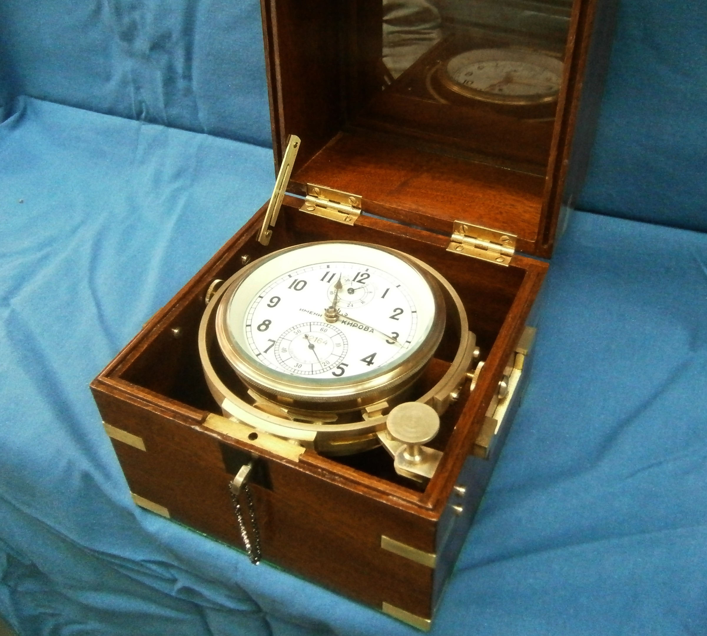
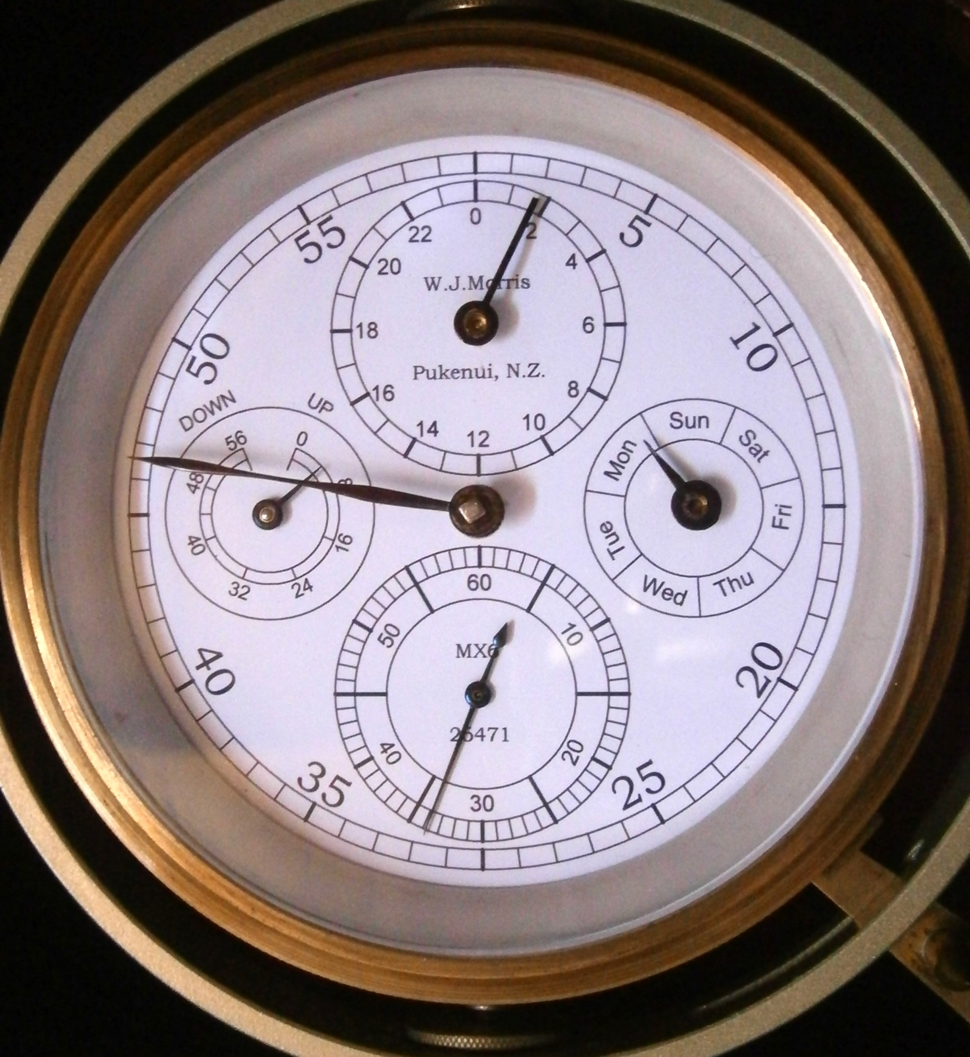
Recently, while checking that a part I had made for a friend would fit in an MX6 chronometer, I broke a perfectly good detent. There was a harsh click followed by a “ping”. I expected the chronometer then to run away but whatever shock had broken the detent spring had also broken the lower escape wheel pivot. The latter I could re-pivot relatively easily by means of a “muff” (see post number 7), but the detent was another matter. Some replacement parts for the MX6 appear for sale on e-bay, but not at a price I am prepared to pay unless absolutely desperate , so I set about making a new one for the first time.

I began by seeking guidance in W J Gazeby’s Watch and Clock Making and Repairing (London, 1953) and he reassuringly begins six pages on the subject by saying that “It has always been a job for the specialist…” He describes how to file up the detent for an English chronometer and how to thin the spring and drill the holes, but it is plain from his description that this is not a job for the beginner. A couple of internet sites also give a brief outline of how to file up a detent from the solid. One maker states that he uses up more than a dozen top quality Swiss files to complete the task. Both gloss over on exactly how one files a spring to a thickness of about 0.08 mm (0.003 in). I have done a fair bit of filing in my time, though never at the scale of a detent, so I rashly set out on developing my own method, a task that was to occupy many of my spare daylight hours for about six weeks.

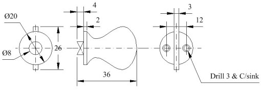
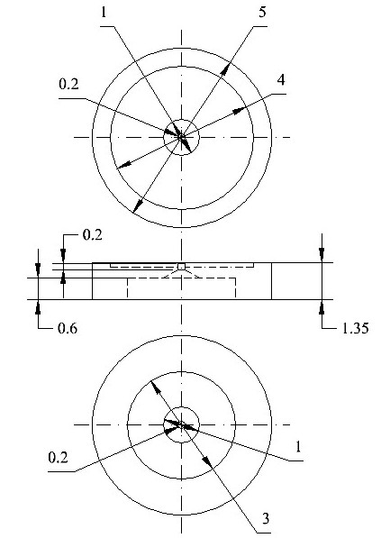
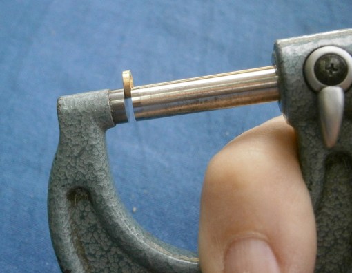
It seemed to me to be a good idea to start with a dimensioned drawing. Enough remained of the broken part for me to be able to piece it together for measurement, using a micrometer to measure thicknesses and a microscope with a moving stage to measure lengths. The latter allows one to measure to 0.1 mm. Lucky owners of a tool maker’s microscope will be able to measure to better than 0.01 mm, but lengths are generally much less critical than thicknesses and in any case I had to make do with what I have.(You can click on figures to enlarge them and use the back arrow to return)

Detent plan

Figure 1: G.A. of detent.

Detent section

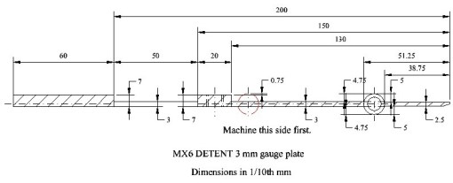
Figure 2: Section through detent.

Note that except for the holes in the foot of the detent, longitudinal dimensions  use the tip of the horn as the datum. This makes setting out dimensions on the workpiece much easier and, as will be seen, is essential if machining rather than filing is used. After several attempts at filing, I found it very difficult, even with the help of a swing tool, to get the lengths and thicknesses located as precisely as I would have wished, but finally, at the fourth attempt, I achieved something acceptable, to me if not to expert watchmakers (Figure 3).

Finished

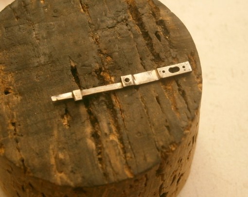
Figure 3: First acceptable attempt by filing.

Admittedly, it looked a bit rough. The pipe was not filed round and the oval hole for the fixing screw was a bit, well, un-oval, but it was true to dimensions. I even got as far as hardening and tempering it, but when I was fixing the unlocking jewel in the pipe, I accidentally knocked over the fixture in which it was being held and the spring broke. In a wakeful moment of that night it came to me that the pipe did not need to be round on the outside as long as the hole through its middle was in the right place and of the right diameter, so that was one hand finishing process that was not needed. Then a barking dog at 2 a.m. reminded me that there is no need to keep a dog and bark oneself. Why should I own a light vertical milling machine and still use a file to produce a complex shape in metal? This is not to say that everything was plane sailing when it came to work out a machining sequence, but once I had done so, and provided I did not make any stupid errors, it became possible to produce an unhardened detent in three hours rather than in two to three days of filing.

This led me to redraw everything from one datum and entering the distances of each change in section and each hole from the datum. I also planned to machine critical surfaces with the end teeth of the 3 mm end mill I used, rather than with the side teeth. With large end mills when cutting with the side teeth, it is the column of the machine that tends to lean away from the cutting forces, while with small ones, it the is flexing of the  mill itself that leads to slightly wedge-shaped parts.

This introduced a slight complication in holding the workpiece. It is not possible to hold something the size of  a detent in a machine vice, so one starts with a large piece, does as much machining as possible and then cuts it off the parent metal for finishing. Thus, I cut off two pieces of 3 mm gauge plate about 30 mm long and milled them square as a pair before reducing one dimension to exactly 26 mm, the over-all length of the detent. I could then hold one of them as a workpiece flat on a pair of parallels with about 5 mm projecting beyond the end of the vice jaws, while the other one occupied the other end of the vice jaws to forestall any tendency of the moving jaw to rotate. Before I did this, however, I milled the 13 x 1 mm notch in one end to form the eventual top of the horn.

As I will recount later, I eventually realised I had to anneal the gauge plate before machining it, by heating it to a red heat for a few minutes and then allowing it to cool slowly while covered in dry sand. This is something the books did not tell me.

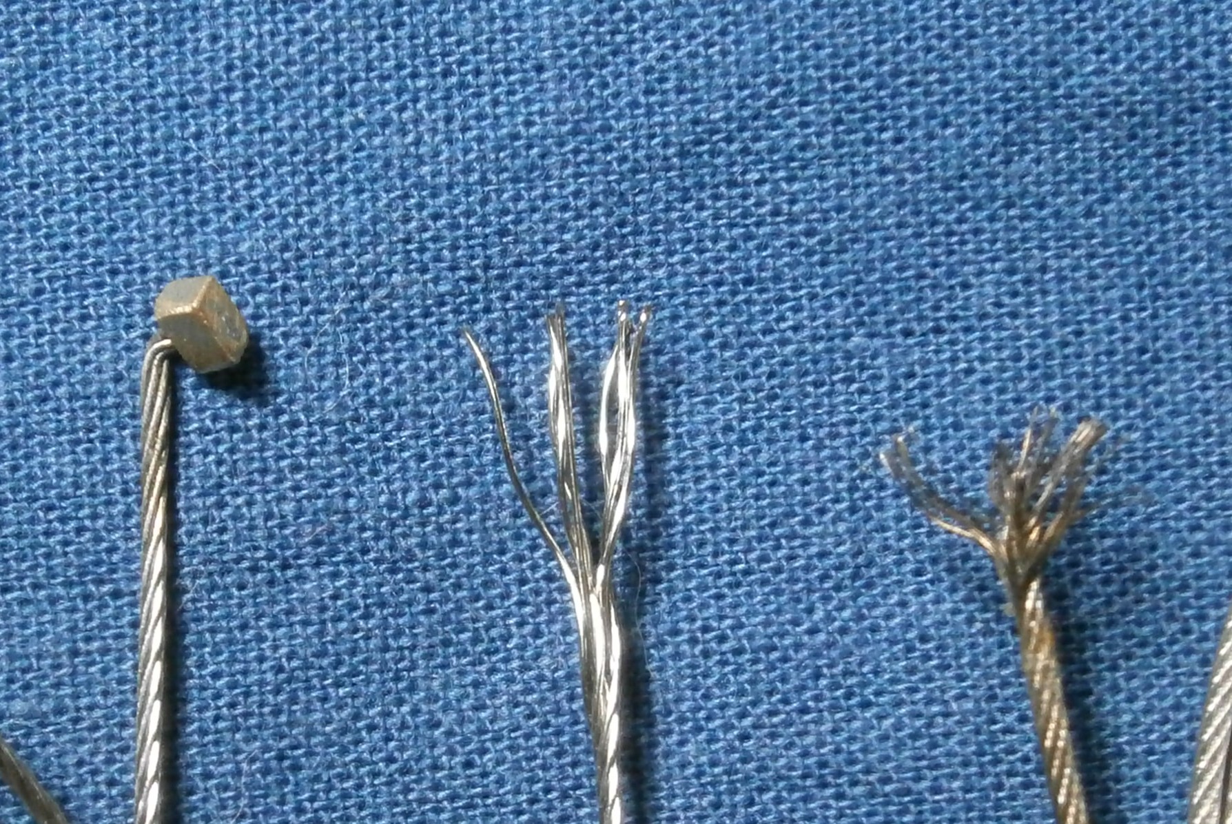
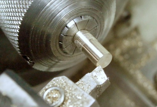
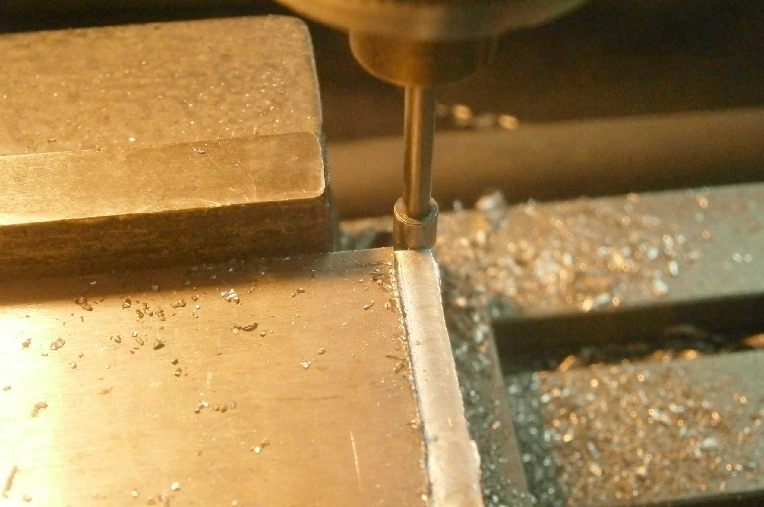
The maximum thickness of the detent, 1.25 mm, is at the pipe, so the first job was to reduce the thickness of the 3 mm plate to this dimension by milling 0.87 mm off each side for a width of about 3.5 mm. I used a large end mill to do this, to save the wear on my one and only sharp 3 mm end mill. It was then necessary to establish the centre line of the milling spindle in relation to the datum. Many years ago I made an edge finder and I wonder how I ever did without it (Figure 4). A true, hardened cylinder on the end of a spring loaded shaft is held in the chuck and rotated at a moderate speed. It wobbles all over the place but is roughly trued with a finger nail and then the workpiece is brought slowly up to it, using the calibrated screw of the machine table. As it begins to make contact, the wobbling reduces until none is discernable and shortly afterwards, as the workpiece is advanced, it suddenly flicks along the edge of the workpiece. At this point, the edge is half the diameter of the cylinder away from the centre line of the machine, and as the diameter of my cylinder is 5 mm, I have only to advance the table 2.5 mm to align the centre line with the edge.

Edge find

Figure 4: Using edge finder to establish datum.

Referring to the drawings, to make the first cut to form the horn the table now needs to be advanced 3.87 mm less the semi-diameter of the end mill, or 2.4 mm, and machined to take off 0.5 mm in thickness to make the first shoulder of the pipe. When the part is eventually turned over to do the other side, the horn will then be the desired 0.25 mm thick (1.25 – 2 x 0.5). The other shoulder of the pipe is machined by advancing the table 5.13 mm plus the semi-diameter of the cutter and taking slightly less off the thickness to give an eventual thickness of 0.3 mm. This surface is extended right to the end of the part so that there is a long flat surface to stabilise it when finishing the spring. The latter’s edges are located in a similar way to those of the pipe and the spring on this side machined to a depth of 0.30 mm, the finished depth, so that only the other side of the spring will need to be filed.

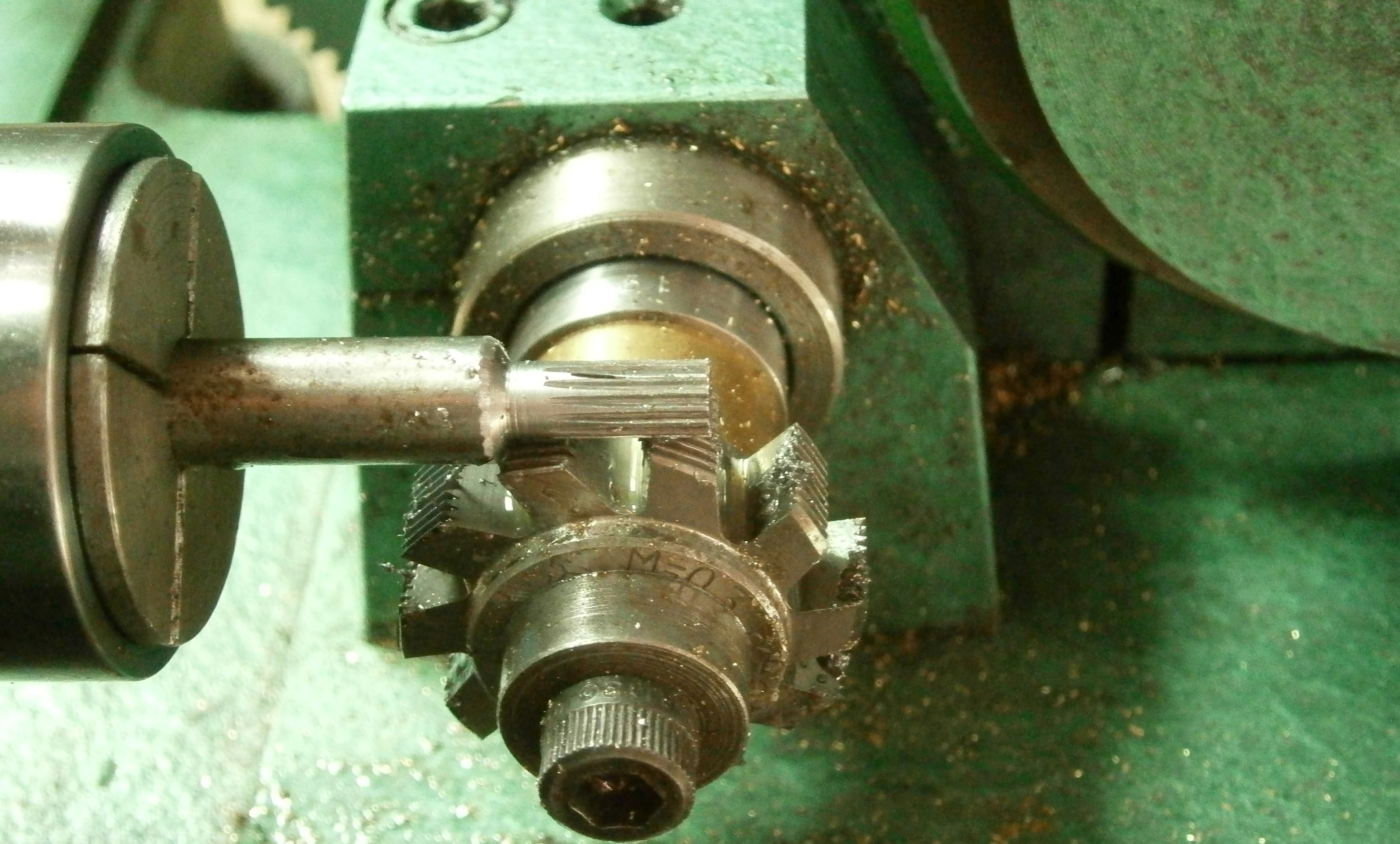
Figure 5 is a posed view of the milling process as it nears completion. Beginners will need to be advised that the workpiece is seated firmly on the parallel by striking it firmly with a soft hammer (I have a large hunk of copper for the purpose) until the parallels cannot be moved beneath it or under the packing piece at the other end of the jaws. In this figure, one can see that I have extended cuts for the various shoulder about half a mill diameter into the parent stock, to ensure  full-height shoulders when the detent is cut off.

Milling

Figure 5: Milling nearing completion.

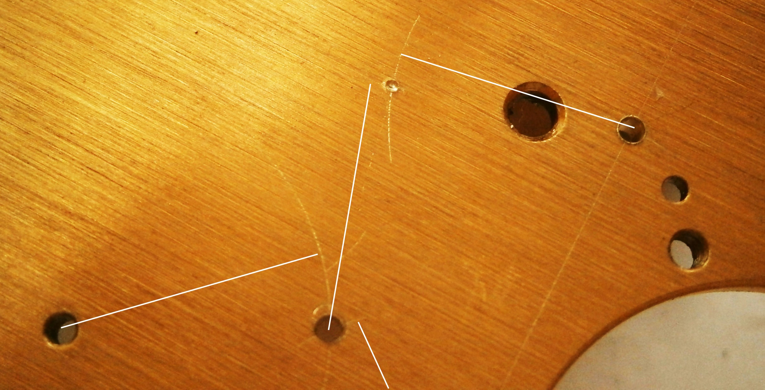
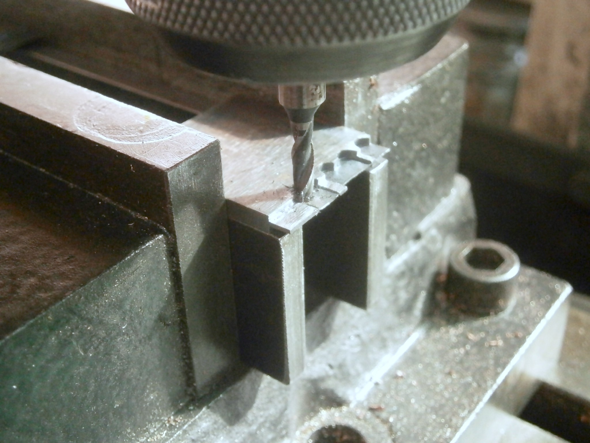
I then turned the piece over, re-set the datum and machined the other side in a similar way. When it came to the spring, I took off only 0.2mm thickness, taking very light cuts, leaving just under 0.2 mm to be removed by filing and polishing. At this point, I used the same datum to locate the holes to be drilled, and used the edge finder to locate the longitudinal centre line to establish drilling co-ordinates. While Gazeby and others seem to locate the holes by measurement and to start them by centre-punching, this will not do here, and any attempt to start a small hole without guidance will lead to wobbling and near-certain breakage. I use the smallest of centre drills to make a starting dimple and the rigidity of the centre drill ensures good centring (Figure 6)

Hole drill

Figure 6: Drilling holes for guide pins.

When buying small drills it pays to buy quality. I was seduced by the very low price of a very large set of small drills, 10 of each in steps of 0.1 mm. When the 0.5 mm drills failed to cut rather than buckle and break I looked at the cutting edges under high magnification and found that they had either no relief behind the cutting edges or very unequal lip angles. The same applied to the majority of drills in this “bargain” set. Happily, I discovered Element 14 (au.element14.com/) who although supplying mainly electronics, stock a wide range of small diameter drills of high quality and who deal with orders the same day. My drilling problems were solved instantly, though drilling with such small drills requires a soft touch with frequent withdrawal of the drill to clear swarf from the holes, and extra care when the drill is about to break through..

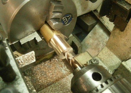
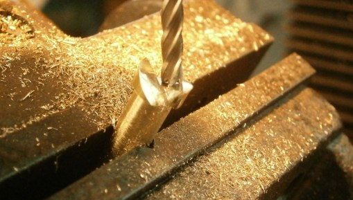
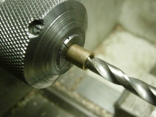
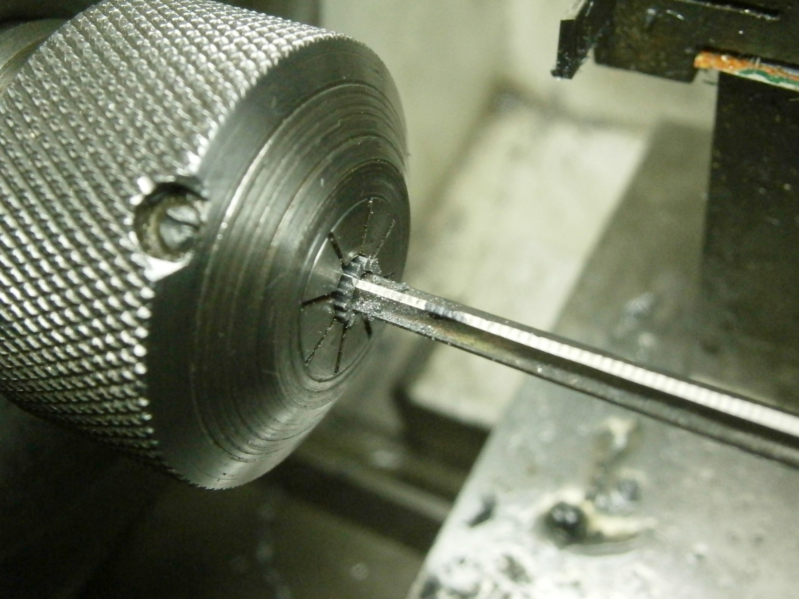
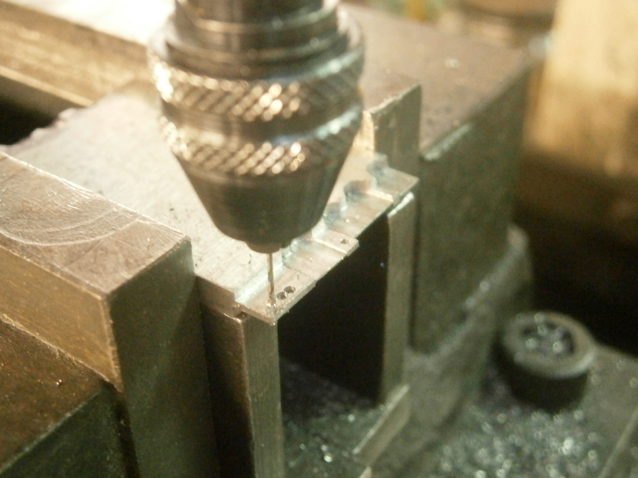
This left the hole for the pipe to be drilled to a little over 2 mm deep (Figure 7).

Pipe drill

Figure 7: Drilling 0.8 mm hole in pipe.

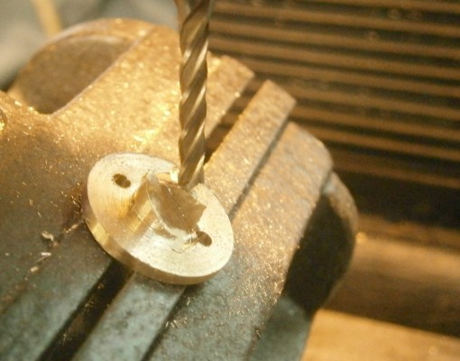
The workpiece can now be transferred to a small vice to convert the two 1 mm holes into a continuous oval. This could of course be done using a slot drill, an end mill with only two cutting edges, designed specifically for this purpose, but I have never seen one as small as 1 mm diameter, and if they exist they are likely to be both expensive and fragile. I used a tiny, round file to join up the holes and make a fairly oval oval. This is also the moment to tap the hole for the screw that attaches the passing spring. Mine is larger than usual at 1 mm, but as I was to make my own screw and passing spring this did not much matter. At this point, the proto-detent can be marked out for separation from the parent metal. I suppose this could be done with a milling machine using a fine slitting saw, but I can do it in less than half the time using a piercing saw, taking great care not to let the delicate blade, having about 25 teeth per cm,  jam and break (Figure 8).

Sawn out 2

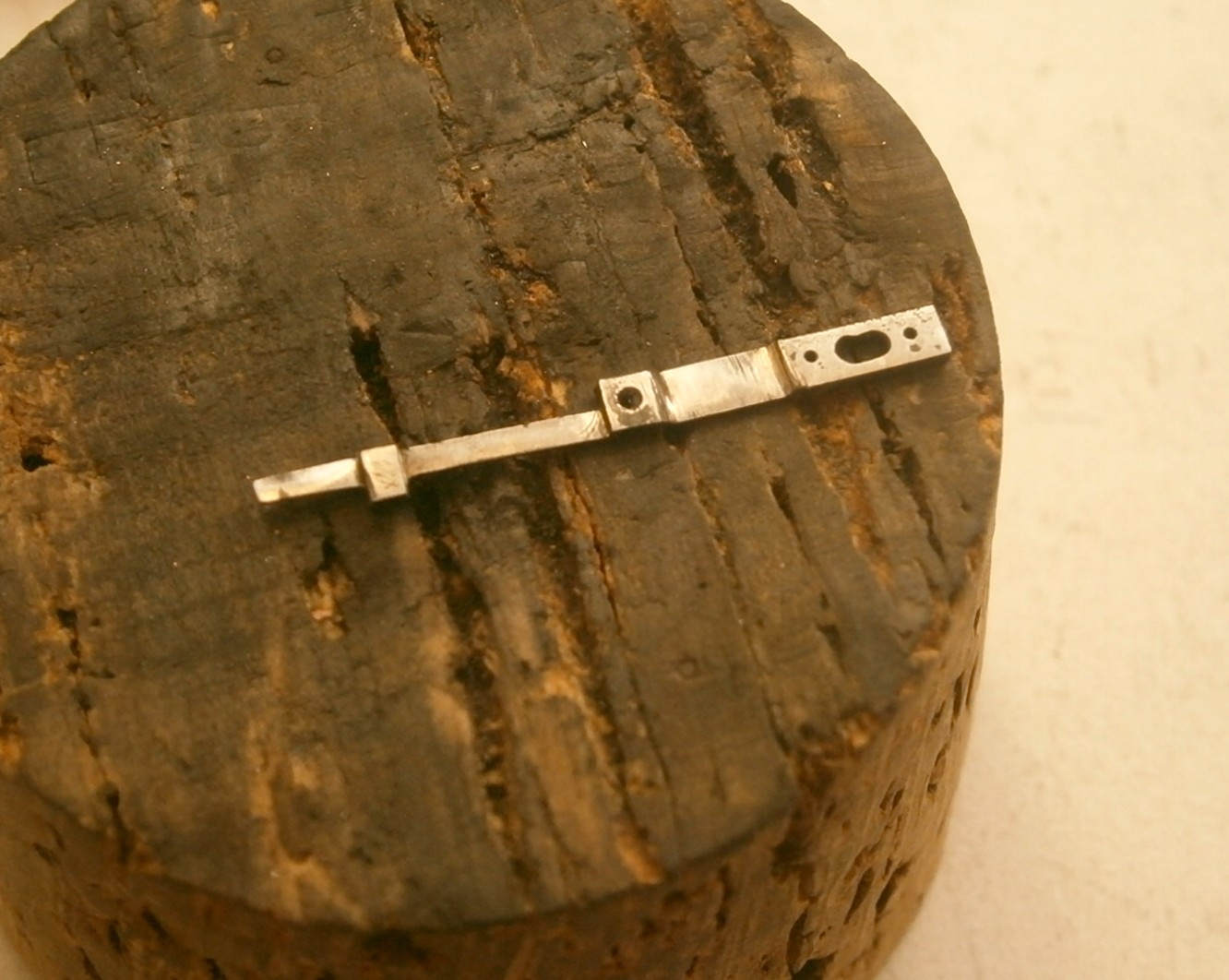
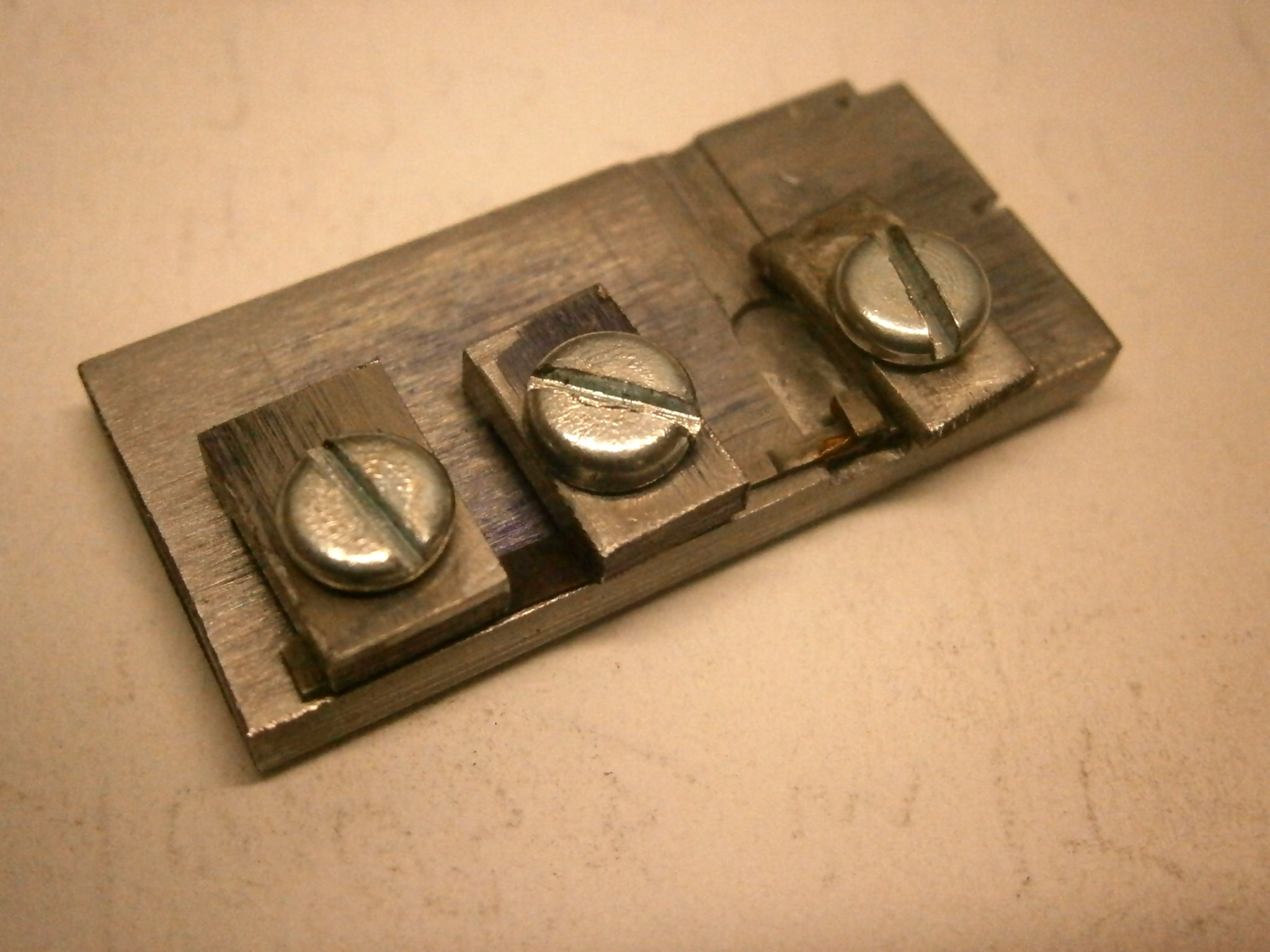
Figure 8: Detent separated from parent metal.

From this point on, the detent needs to be handled carefully,  as it is all too easy to catch it on something and bend it beyond redemption. When hard, it is extremely brittle and even after tempering it remains somewhat delicate. The first task is to file up the lower edge of the detent to the scribed line, including the lower edge of the pipe. The drawings show that the foot and the block for the passing spring hole are of the same thickness, so this part can be held in a vice and filed with a certain exuberance, but the pipe is thicker and does not take kindly to being squeezed hard in a vice, so a gentler touch is needed for the horn and the pipe.

While still in a fairly strong state it makes sense to draw file and polish as much as possible. A check with the section drawing shows that everything between the pipe and the end of the detent, excepting the spring , is on one level, so it can be rested on this surface to deal with the other side, provided that the pipe is rested in some sort of depression, say a groove in a piece of scrap metal, wood or cork, to prevent a bend forming. While the spring is still relatively strong its back can be gently cleaned up to remove machining marks and given a preliminary polish.The back of the tip of the horn needs to have a bevel for the escape wheel teeth to slide off and the front needs to have a square seat of good finish for the tip of the passing spring.

The spring, which I have discovered to be the pons asinorum of detent making, can be next. The old (and some modern) accounts suggest resting it on a block of cork with a slip of cork behind the surface being filed to support it, but a swing tool allows everything to be kept flat and to be filed to a more-or-less precise thickness. Unfortunately, such tools cost about 800 Euros new, so I made my own last year and described how to do it in “Model Engineers’ Workshop”. As the back of the spring has been reduced by 0.30 mm, positive support is given by cutting a 5 mm wide slip of 0.30 mm feeler gauge and sliding it beneath the spring and the support surface. The piece of ground-flat stock on which the detent rests in Figure 9 has a variety of grooves cut into it to accommodate the pipe.

Detent 2 012

Figure 9: Detent held in swing tool to file spring.

In my swing tool, the top of which is shown in Figure 9, a closely fitting square plunger slides up or down inside an outer casing, the top of which is provided with a dead hard surface. The plunger’s position is set by means of a calibrated screw, so that the workpiece may be raised in steps of 0.01 mm  if necessary, and when the file starts to slide across the hardened area instead of cutting the workpiece, a further adjustment can be made to bring the part to the desired thickness. The whole tool swings between trunnions so that if there is any tendency for one end of the file to lift, the tool swings to correct it. The business surface of the file should be checked to see that it is flat. I use a fairly coarse “four square” swiss file to remove most of the metal and mark the flattest of the four cutting surfaces. As the spring approaches the desired 0.08 mm thickness, as measured by means of a micrometer with clean measuring faces, I switch to finer files and leave 0.01 mm to allow for polishing and bringing it to its final thickness.

By the time I had managed to machine and file an acceptable detent I had to turn my mind to hardening and tempering it by my usual method of surrounding it with case hardening compound (Kasenit, Cherry Red, etc), bringing it to red heat and decanting it into water. The compound not only prevents the thin spring from burning up in the flame, but also refines the surface grain of the material, so reducing the tendency to crack. The gauge plate is already alloyed to maintain a fine grain structure, so the compound simply protects the detent from burning. The traditional method involves wrapping it with fine iron wire and soft soap – if one can find either nowadays.

In the hardened state, the detent spring is in an extremely brittle state and easily broken as I twice accidentally discoved, so one should waste no time in tempering it. This can be done by heating it on a bed of dry sand with a piece of polished feeler gauge or a clean old ball bearing alongside so that the tempering colour can be seen and the detent removed from the sand as soon as it passes dark brown and reaches a purple-blue colour, but much easier is to put it in an electric oven set at 250 Celsius. My first two detents came out of the process with a slight longitudinal bend and one broke when I tried to correct this. I softened the other one by heating it, corrected the bend and re-hardened and re-tempered it, only for the bend to reappear, but this one did not break when I straightened it. On a trial fitting it became obvious that the horn of the dentent was canted upwards slightly and the pipe axis was tilted sideways, so a longitudinal twist had been added to a bend.

This led me to make the little jig shown in Figure 10, in which tiny dogs hold the foot rigidly in place while the other two dogs bear lightly on the passing spring block and the horn of the detent. A slip o 0.30 mm feeler gauge guards against buckling of the spring

Harden jig

Figure 10: Jig to prevent distortion.

The whole could then be hardened and tempered before removing the detent from the jig (Figure 11)

OLYMPUS DIGITAL CAMERA

Figure 11: Hardening jig with tempering tell-tale.

This unfotunately did not prevent the upward cant of the horn, so I cut out yet another detent and let my brain think about the problem during the small hours of the morning. Professional engineers will have immediately divined the problem, but it took me several days and three detents to realise what was happening.

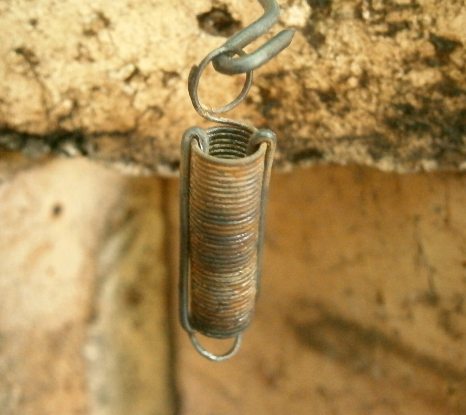
Steel plate is made by rolling at red heat and so-called “hot-rolled” steel is recognisable by being covered with a black scale and being only of nominal dimensions. If the scale is then removed chemically and the steel rolled cold between smooth rollers, it can be brought close to nominal dimensions, but the rolling leaves stresses locked up in the steel and these stresses can be released by machining and by heating, both of which my proto-detents had suffered. Once I had annealed the workpiece before machining it, my distortion problems disappeared. I also abandoned my little jig and case hardening compound in favour of placing the detent inside a small steel spring to shield it from the flame (Figure 12).

Harden device

Figure 12: Hardening container.

The lower end of the device has a short steel plug to stop the detent from dropping out and the spring is prevented from extending at red heat by two wire bridles which hold the coils together. The whole is heated to a “bright cherry red” and then dunked into water, taking care  that it remains upright until completely submerged and cooled, as to let one side of the workpiece cool before the other is to invite severe distortion, even with previously annealed material.

This left only polishing to finish the detent itself and fitting the guide pins, locking jewel and passing spring. I am in two minds about the necessity of polishing and perhaps readers will let me have their views. It seems to be important from a cosmetic point of view in chronometers, as witnessed by the engine turning and other beautiful patterns to be found on chronometer plates, which would normally be seen only by clockmakers at overhaul. It can also be argued that a high polish tends to prevent dust from sticking to form a nucleus for rust. In the case of a spring, a fine finish is desirable, as scratches and machining marks may form an area of increased stress, from which cracks may propagate. On the other hand, an oxide film forms a protective layer against rust, one of the reason why screws and hands are often blued or blackened . I polished my spring and the tip of the horn very carefully and was less attentive to the rest, reasoning that the longer I spent at the task the longer the spring would be at risk.

The guide pins of the original detent were tiny taper pins of about 0.45 mm diameter. The smallest taper pins I have are a little larger and in any case I did not have any 0.45 mm drills, so I settled for 0.5 mm holes and larger pins, which I drove home (Figure 13 shows this for an early, distorted detent) before filing the business ends to fit in the guide slot. I melted a little flake shellac around each pin to make sure that they do not work loose.

Pins drive

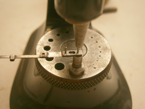
Figure 13: Driving home taper pins.


I have covered fitting the locking jewel in post number 15, and it presented no more than the usual problems of locating a tiny sliver of ruby in its correct orientation in a hole only 0.8 mm in diameter and 2 mm long.

I was surprised to find that the passing spring presented very few problems that could not be overcome by trying again. I made it out of 0.05 mm brass shim stock, which is easily cut to shape with small nail scissors, first drilling a hole to form a datum for everything else. Brass work hardens and becomes springy, and as the shim is produced by rolling, it is work hardened to some extent, so that as the spring is cut out, it tends to curl up. This is not necessarily a disadvantage, since the process of straightening it to the desired shape continues the hardening process. I found that it was relatively easy to correct bends and twists by drawing it between two finger nails. Although the spring appears to be very weak and vulnerable, its elastic limit is very unlikely to be exceeded in normal use. Once fitted and its screw driven home, I surrounded the base with a little melted shellac to ensure that it stayed where it was. I then cut the spring to length. About 0.5 mm seems to be about right.

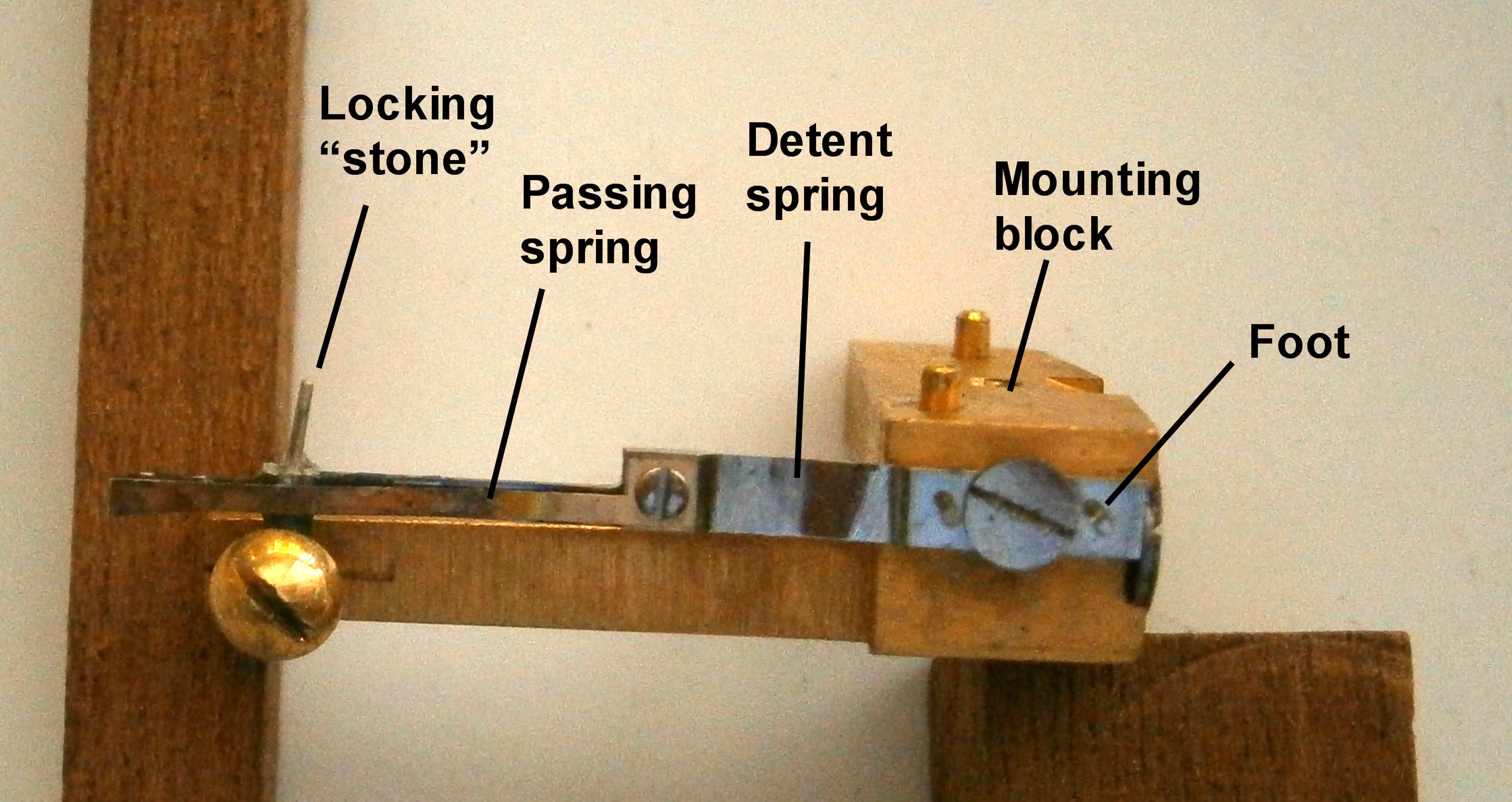
Figure 14 shows the finished detent fitted to its support block. The polish is better than it looks in the photograph.

On carrier

Figure 14: Finished detent in support block

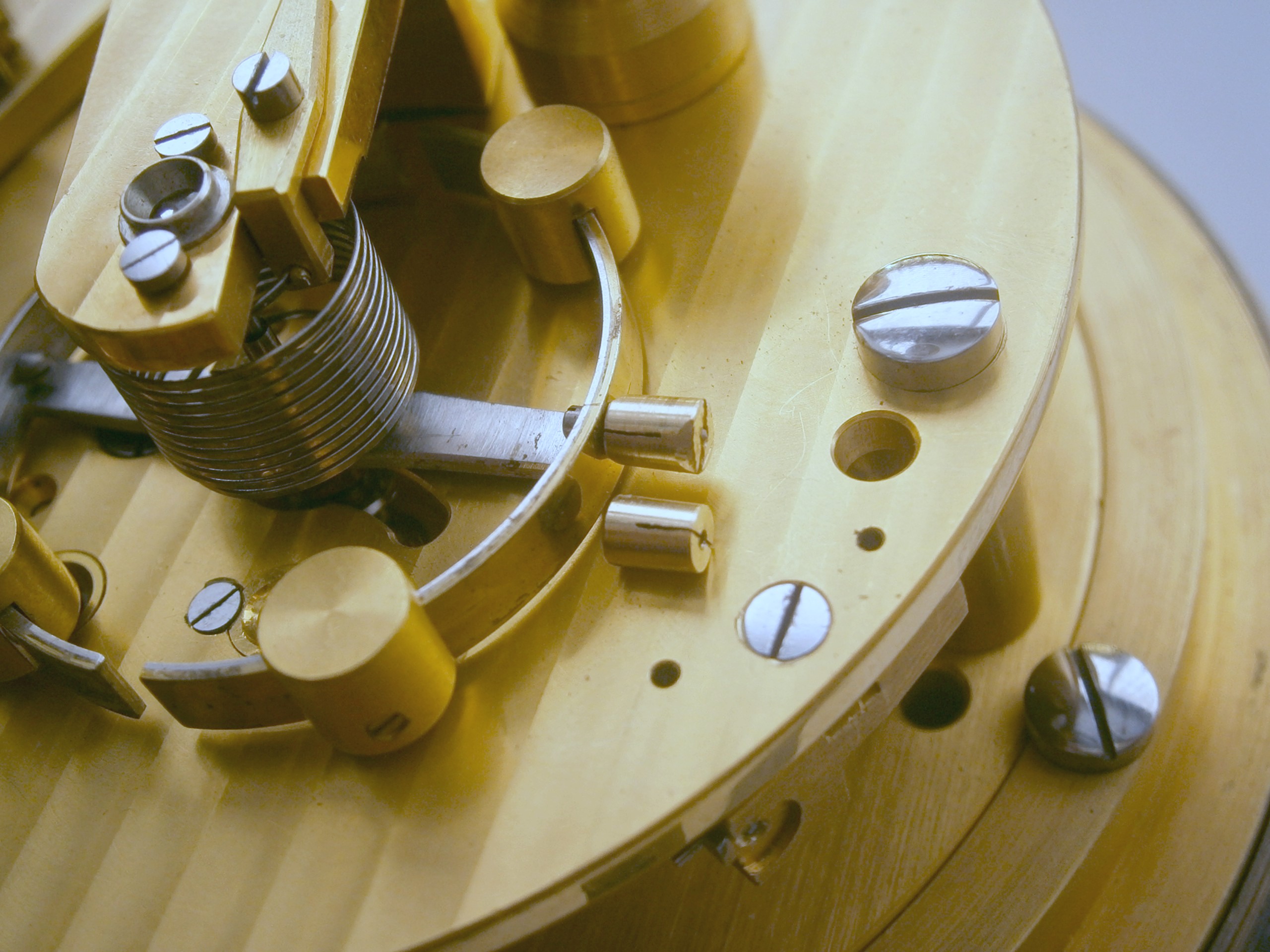
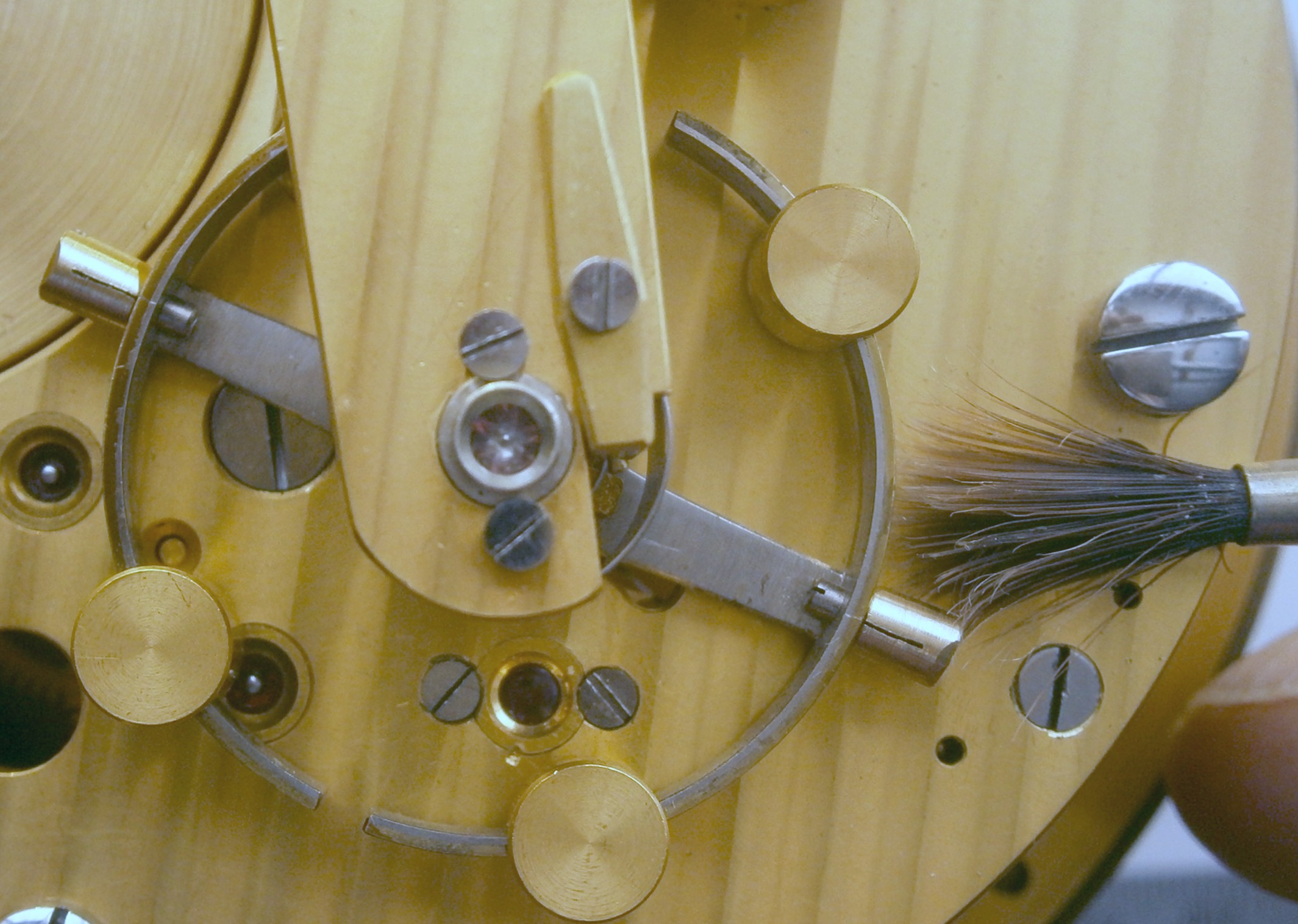
When fitting the detent, it is best to remove the balance wheel so that the engagement of the escape wheel teeth with the locking jewel can be clearly seen. The movement should of course be blocked, but enough free movement of the escape wheel is possible to check that a tooth covers about one third of the face of the locking jewel when engaged and that the pipe rests against the face of the banking screw when a tooth is not engaged, while the lower end of the pipe should not drag across its threads.

Before fitting the balance wheel, it is wise to slacken off the adjusting screw and to slide the detent back on its block so that the foot of the detent rests against the screw head. This reduces the chance of the unlocking jewel striking the back of the horn and possibly breaking the jewel. Once the balance wheel is fitted, check that the horn is not fouling the underside of the unlocking roller, though this will usually be obvious because the lower balance pivot will refuse to sit in its hole. Obtain a good view of the roller and, rotating the balance with a delicate finger, observe how the jewel interacts with the passing spring, advancing the detent  a little at a time until the jewel lifts the passing spring off the horn one way and the locking jewel off the escape wheel teeth the other. The unlocking jewel should unlock the teeth of the escape wheel plus an allowance for shake in the pivots (which should be negligible in a good chronometer), plus a little more, the amount to be decided by the behaviour of the balance. At this point, the movement can be unblocked  and the balance again moved by hand to watch the interaction of the detent and escape wheel.

The balance can then be set in motion and with any luck, the instrument will spring into life again and build up to a healthy motion of the balance wheel. Some tweaking of the detent position may be needed to prevent tripping (skipping of teeth) and to ensure that the balance receives adequate impulse before locking occurs, but it is always wise to block the movement every time before making any adjustment, bearing in mind that the range of adjustment is tiny, no more than the overlap of the passing spring on the horn of the detent. In fact, the angle between the unlocking and impulse stones is a rather more important factor in preventing skipping and achieving good acceleration, but if the chronometer was running before the detent broke, this should not need adjustment. Altering the depth of engagement of the locking jewel with the escape wheel teeth seems best left at one third.

After a couple of days to settle down, my chronometer now has a very respectable rate of less than half a second a day with a strong action, so my weeks of experimentation seem not to have been wasted. Some more details on chronometer adjustment may be found in Appendix 1 of my book The Mariner’s Chronometer available for purchase through Amazon.com.


21: A Balancing act.

22 04 2016

A little while ago, a friend in South Korea sent me two balances from Soviet MX6 chronometers, to see if I could get them to run to time. One he had found impossible to get slow enough with the available range of adjustment of the timing weights and the other he could not get fast enough.

I first checked the physical dimensions of the balance wheel and its associated rollers and springs and all were very closely similar. The timing weights  were all 4 mm in diameter give or take 0.01 mm and all of the same length. All were 0.40 grams within the limits of precision of my electronic balance, which reads to a precision of 0.01 g (for the record, the whole balance without the spring but with rollers weighs about 12 grams). That left only the elasticity of the springs and as I am not equipped to investigate that , I surmised that in assembling the chronometers, selective assembly may have been used, so that fast springs might have been matched with balances of greater inertia.

I was not about to meddle with the springs, which looked perfectly normal to me, so that left only the timing weights. The fast balance was relatively easy to deal with, by adding weight to the timing weights. My friend had used Blu tack with some success. Tempting as it was to take the quick way out and add a blob of solder to each side and then file it off until each weight was equal, I decided to make a proper job if it by fitting tiny sleeves to the weights. It was a simple matter to turn down a piece of brass bar to a diameter of 5 mm, drill and ream it to 4 mm and part off 3 mm lengths, then cutting  diagonal splits so that it could be sprung in or out if required. As it happened, I was lucky, in that both sleeves weighed exactly the same. To fit closely on the existing timing wights, they had to be sprung in a little, and Figure 1 shows them in place (if you wish, the figures may be enlarged by clicking on them. Return to the text using the back arrow).

Sleeves 001

Figure 1: Close up view of sleeves.

It was then a simple matter to bring the balance to time by fitting it to one of my chronometers and following the procedure outlined in post 13 of this blog. At first, I  timed it every ten minutes, making at first large adjustments and then homing in with ever smaller adjustments over longer intervals, until it was within one second in 12 hours, quite good enough for me and, I hope, for my friend.

The slow balance was more difficult, as it required smaller balance weights. The diameter of the studs on which the weights are screwed is a mere 1 mm, so any new weight I made would need an M 1 thread to be tapped through it and, as it was not possible to predict in advance how much smaller the weight needed to be, I was in for more work that I had realised. I decided to keep the length constant at 4 mm and vary the diameter. I chose 3 mm for a  first attempt. Once a piece of bar had been tuned down to this diameter, it had to be drilled the tapping size for M 1 screws. Getting a 0.8 mm diameter drill to start on centre needs care as, if the drill point starts to wobble, it will not be long before the drill decides to cut off-centre and then break. My solution was to use my smallest centre drill to make a dimple in the end of the bar, just deep enough to start the 0.8 mm drill, and then to back out the drill every milllimetre to clear it of swarf that might cause it to jam and then break.

Once drilled, the piece could then be parted off at 4 mm and chucked to face the other end. Tapping one of these small pieces without breaking the tap requires great care (Figure 2 shows how fragile the tap looks; the ruler is 12.5 mm wide). Usually, brass is turned dry, but an attempt to tap it dry will sooner or later lead to a squeaking noise which, if prolonged will lead to the tap jamming and then breaking, so I have a little pot of extreme pressure oil on my bench to avoid just such a scenario, as taps of this size are very costly. Once a pair of weights have been turned, drilled, parted off, faced and tapped they can be weighed and, if significantly different in weight, a little turned off one face of the heavier weight until both are the same.

Tap

Figure 2: Metric no 1 tap.

The weights then need to be slit longitudinally over most of their length so that the threads can be sprung together to increase the resistance to turning on the studs. If left slack, they will unscrew themselves, eventually fouling  the upper balance cock and bringing the chronometer to a halt. I don’t know how this might be done as a production process using a fine slitting saw. I did it with a piercing saw fitted with the finest blade available. The other end then needs to be slit at right angles to the first cut with a wider saw for a depth of about half a millimeter to form a screw driver slot. The ends of the long slot can be squeezed together with a pair of brass-faced pliers until there is definite resistance to turning the weight by the fingers.

This, my first attempt, weighed in at 0.21 g and was too small, as now the balance could not be got slow enough without the weights fouling the balance cock, so I tried again with a diameter of 3.2 mm, weight 0.24 g. Figure 3 shows one of my first pair alongside the final attempt Now it was so nearly fast enough with the weights screwed fully in that I succumbed to impatience and filed a little off both ends of both weights. My impatience was rewarded and the balance now kept time within 2 seconds a day with the weights screwed out about half a turn.

Cylinders 003

Figure 3: 3.2 mm weight (fitted) with 3 mm weight alongside.

A few words about stopping the balance and adjusting the weights with it in place may save some anguish. If you have a delicate touch, you can stop the balance by using your finger tip, but you may find out that your touch is not quite delicate enough when one or both balance staff pivots break off, so I advise using a small and soft camel hair artist’s brush which I feed in from the side, with it brushing against the timing weights until the balance eventually comes to a safe halt (Figure 4). Note that the brush is at about a right angle to the balance cock as this is where the balance will come to rest (see also Fig 3).

Brush stop

Figure 4: Stopping balance with a brush.

There is no substitute for a delicate touch when it comes to adjusting the weights. If you simply jam a screwdriver into the slots, sooner or later you will break something and it will be painful to your bank balance. Steady the balance with a brush applied to one weight while you deliberately approach the slot in the other with enough magnification to see clearly the slot that your screwdriver tip is aiming for. Provided that your screwdriver tip is in good condition, almost a sharp edge, it needs only to be resting in the slot. You are not driving the weight home. You are coaxing it round. There should be no up or downwards pressure exerted if you value your pivots.

If you ever have to transport a chronometer, it is important to immobilize the balance. Typically, this was done by using tiny wedges of cork underneath the arms of the balance, called “corking the balance, but a little safer to apply is to use six small slips of notepaper folded in two as shown in Figure 5. It is more difficult to break something with paper, and if the top pivot is already broken, the paper will still work to some extent.

stopping-balance-for-transport-001

Figure 5: Blocking balance wheel.