I recently acquired a damaged chronometer that seemed to have been dropped on to a hard surface while out of its bowl, or perhaps the owner had thrown it at a wall in frustration. At any rate, the walls of the fusee track had been squashed in at one point and had trapped the chain. By carefully using a small screwdriver whose edges had been rounded off, I was able to open out the track and a fine file removed all other traces of the injury to the fusee. On further inspection I found a large range of problems that would need to be fixed before the chronometer could be brought back to life, some of them probably due to the shock of the fall and others probably consequent on the initial damage.
The most obvious was that all the pivots of the balance and escape wheels were broken, which I could fix, and two of the escapement hole jewels were shattered, which I could not, so I was committed to having to buy replacement jewels. In the Hamilton M21 chronometer, these jewels are friction fitted in the holes in the plates and so are rather more difficult to fit than those of most other chronometers. The locking jewel was broken off flush with the top of the detent, but happily, enough remained for me to be able to photograph, so that its expensive little replacement could be replaced at the correct angle of 8 to 12 degrees of draw. The detent spring was also bent out of shape, but I was able to straighten it using the method outlined in Post 28.
To the naked eye, the escape wheel looked fine, apart from the disaster to the pivots, but on closer inspection its teeth looked worn and when viewed under a low power microscope, the tips and sides of the teeth looked worn, as shown in Figure 1.

Figure 1: Worn and damaged escape wheel teeth.
Normally, only the tips and front faces of the teeth come into contact with anything, i.e. the locking jewel and the impulse jewel. Its manufactured diameter would have lain between 13.14 and 13.18 mm, but its measured diameter was only 12.73 mm, a relatively enormous disparity, so I guess that something had caused the escape wheel to “run away”, the while battering itself against a jewel, eventually breaking the locking jewel and, as I found later, badly chipping the impulse jewel. Perhaps, when the first escape wheel pivot broke, perhaps it was still able to run, albeit drunkenly, and so damage the sides of the teeth.
I searched for a new escape wheel, but could not find one to buy. Most chronometer escape wheels seem to have fifteen or thirteen teeth, but Hamilton chose sixteen, so the readily available Soviet MX6 escape wheel (a bargain at US$ 235 with pinion?) could not be substituted. I had to bite the bullet and try to make one myself. A quick trawl of the internet showed that two people had made escape wheels by laboriously making a punch and a die, so that the wheel could be punched out of sheet metal with the dimensions and crossings all ready formed for machining the teeth. This method did not appeal to me, and anyway, for me part of the pleasure of restoring these instrument comes from using old techniques. A punch and die are fine if you want to make lots, and Hamilton eventually made over 11,000, but for a one-off, it seemed to me to be overkill.
Figure 2 is a posed photograph of how to remove an escape wheel from its arbor.

Figure 2: Removing wheel from arbor.
Note how a slot in a scrap piece of brass protects the collet from damage, while the arbor is punched out. Beginners in the use of a staking tool perhaps need to be reminded to check the depth as well as the diameter of the hole in the punch, so that they do not inadvertently damage the pivot. The photos in what follows were taken while developing a method over several days, so the keen-eyed reader may notice certain lapses in continuity…
Some makers start by cutting out or buying a circle of brass, mounting it on an arbor, turning it to size and then cutting the teeth. This works well with larger wheels, but because of the small size of the hole in the middle, this makes securing the blank a bit uncertain for turning and the set up lacks rigidity when it comes to cutting the teeth. I used the more wasteful but safer method of machining the teeth on brass rod and then parting off slices, so I could have several goes at developing my method. After turning the rod down to the outside diameter of 13.16 mm, I transferred the chuck from the lathe to my dividing head in a bid to retain concentricity. Figure 3 shows the faces of the teeth being cut.

Figure 3: Cutting the front of the teeth.
Although the photo shows the work piece in a three jaw chuck, I found that the set up would not hold concentricity between lathe and dividing head to any better than 0.03 mm, so I eventually used a four jaw chuck and centred the piece with a dial indicator against a register machined on the bar. To cut the teeth, I used a fly cutter filed from a piece of 6 mm silver steel and then hardened, tempered and polished on the cutting faces. Run at 1,500 r.p.m this gave an excellent finish that needed little polishing. Tools for cutting brass need to be sharp. Note that the acute angle of the teeth of about 60 degrees means that the front edge of the tool needs to be lowered below centre by just over 2mm.
It was somewhat more difficult to machine the curved back faces of the teeth, but I eventually managed to file a radius of 2.5 mm on the end of a piece of silver steel and to form the all-important relief behind the cutting edge.
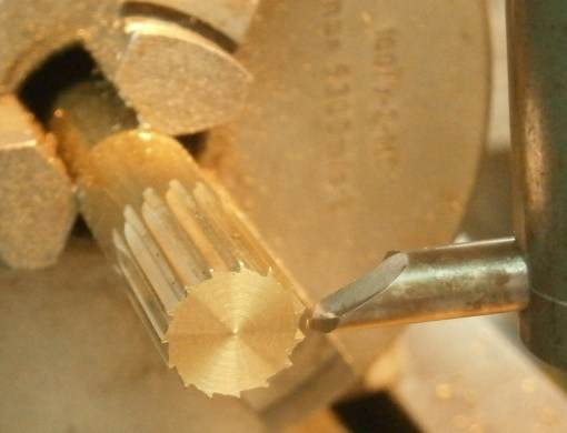
Figure 3: Back faces of tooth being cut.
Setting the tool height to get the tooth looking correct needs to be combined with rotating the work piece to get a tooth that is robust enough and to leave a narrow land at the top of the tooth, specified as 0.13 to 0.14 mm wide. Of course, this cannot be easily measured and for myself I modified that specification to be “land present and just about visible”. In this photograph of an early attempt, the land is a little too wide, but the form looks fine. If you take too much off, the diameter inevitably has to be reduced to restore the land.
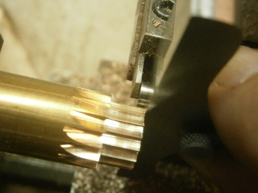
Figure 4: Parting off.
Most turners will agree that “Parting off is such sweet sorrow”. The tool needs to be sharp with its face square to its axis, and the axis has to be square to the axis of the lathe. The cutting edge needs to be exactly at centre height or, with a back tool post, a minute amount above. With the work piece transferred back to the lathe begins the task of parting off slices while ensuring that no slice is thinner than 1.32 mm. As the conditions above are difficult to meet exactly, it is better to part off oversize and then face the slices down to the desired thickness. Measuring small distances in a confined space is best not done with a ruler, and I use a depth micrometer, as shown in Figure 4. Parting off is easier if there is a central hole and I finally remembered to drill this before parting off.
I then turned a holding fixture which would not leave the lathe until all the slices had been reduced to the correct thickness, though I eventually realised that Hamilton’s specifications and tolerances were to ensure interchangeability and that 0.1 mm either way was of little importance as long as it is no wider than the impulse roller. Figure 5 shows the simple fixture being bored to produce a recess 1 mm deep that would just accept a slice of embryo escape wheel.

Figure 5: Boring fixture.
Knowing the depth of the recess from the outer shoulder, it was then possible to set a facing tool back from this shoulder, using the graduations on the tool slide, by an amount to give an over all thickness of 1.27 to 1.32 mm.
At first, I used shellac to secure the wheel in place, but found that the fixture combined with the mass of the chuck formed such a large heat sink that it was difficult to reach a high enough temperature with a small flame, a problem not eased by relieving the end of the fixture with a deep slot, seen in some of the following photographs. Eventually, I used superglue. It melts at a much higher temperature than shellac, so I was obliged to remove the fixture from the lathe and soak it in acetone overnight to release the wheel.

Figure 6: Initial counterbore.
Having cemented the part into place and faced it to the correct thickness, the counter bore in the wheel can be started using an 8 mm end mill or slot drill, its depth controlled by the graduations on the tail stock quill. This counterbore is then opened out with a boring tool (Figure 7) to its correct depth and diameter.
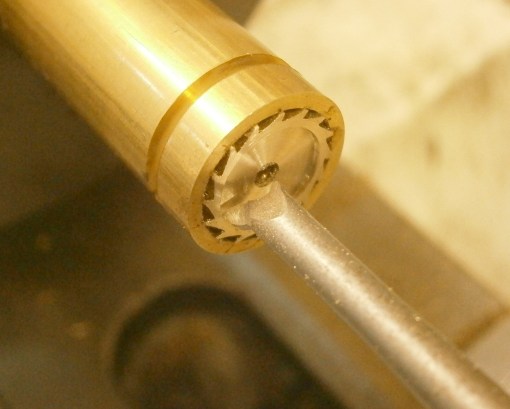
Figure 7: Counterbore enlarged.
The correct diameter removes just a little of the root of the tooth to give the finish shown in Figure 8. To ensure concentricity of the hole in the centre and the tips of the teeth, I ran a small but rigid reamer, with one of its two end teeth ground back to make of it a small but rigid tool. A reamer is usually used to size a hole and will normally follow the existing hole, but in this case, only a whisker was removed, and in any case, the hole is too small for a conventional single point boring tool to enter.
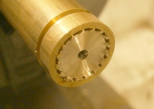
Figure 8: Counterbore completed.
After giving it a good soak in acetone the wheel could be removed from the fixture so that marking out for the crossings could begin. I faced the ends of a piece of wooden dowel and glued to each end a piece of emery paper, one of 800 and one of 1200 grit and rotated the dowel against the floor of the counterbore to remove most of the turning marks prior to marking out. In a scrap of brass, I faced, drilled and reamed a 3 mm hole and made a close fitting removable spigot, one end of which was turned down to a close fit in the hole. Before parting off the spigot I made a minute centre mark in it with a sewing needle held in the tailstock chuck (Figure 9).

Figure 9: Marking out jig.
From this centre I scribed a circle of radius of about 18 mm and divided it into 6 parts by the well-known method of stepping the dividers around it at the same radius. I marked out centres on three of the radii at a radius of 13 mm and from these centres scribed the outlines of the spokes, adjusting the radius by trial and error to give sufficient metal at the joining of the spokes with the periphery, which has a radius of about 5.5 mm. Midway between the spokes and the periphery I made punch marks and then removed the wheel from the jig to drill 2 mm holes at these points. Figure 10 shows a wheel at this stage.

Figure 10: Ready for crossing out.
The purpose of the holes is to allow entry for the blade of a piercing saw, in this case a new 4/0 blade, but before beginning to saw, some filing makes subsequent sawing and filing much easier. I long ago made myself a mini four square file by grinding away two adjacent sides to make safe edges and I used it to file in and out to the marked lines, so the the saw could start right next to the line (Figure 11).
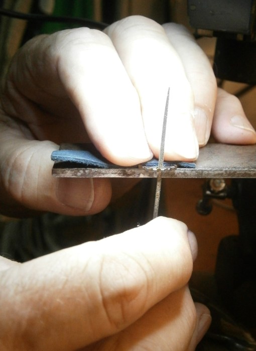
Figure 11: Preliminary filing to lines.
The wheel is much too fragile to be held in a vice and Figure 11 shows how it is held horizontally between fingers and a horizontal surface while the file moves up and down. It helps greatly to be able to see exactly where the file (or saw blade) is going and I have a binocular microscope mounted on a boom on my work bench. Note too the piece of leather between my fingers and the wheel. The teeth of the wheel by this stage are sharp! A later photo (Figure 13) taken before this one shows my fingers before I learned this important lesson. Figure 12 shows a wheel prior to sawing.
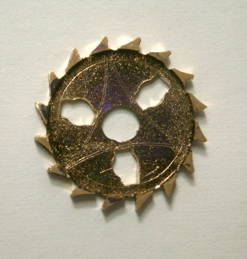
Figure 12: Preliminary filing completed.
Sawing could now commence, again holding the wheel horizontal, as is usual when using a piercing saw (Figure 13). The saw “table” is simply a strip of metal cantilevered from a small vice to give the hand room to move up and down beneath it, and the wheel is rotated to keep the blade tangential to any curve as the cut progresses. When progressing around tight curves or into corners, the blade must be near-vertical, but around shallow curves or in straight lines the blade seems to follow the lines better if canted forwards a little, as shown in the figure.
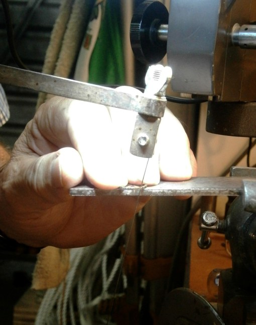
Figure 13: Crossing out with saw.
It will, I hope, be obvious after a little thought that only half of each crossing can be sawed this way and for the other half the wheel must be transferred to the other side of the table and the saw held in the left hand. This needs more ambidexterity than I have, so I simply reversed the blade in the frame, so that the teeth faced inwards towards the frame, and sawed backwards towards myself. (See Fergus’s comment) Figure 14 shows the results in an early, practice attempt to assess the practicality of making the crossing by hand.
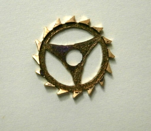
Figure 14: Ready to file again.
The rest involves filing to the lines. The closer one can saw to the lines, the less filing is required. Swiss needle files are needed and there is a particular form used for crossing out and it is called a crossing file; both surfaces are curved with different radii and tapering to a point, so with care, finely rounded internal corners can be cut. A crochet file is useful for getting into sharp corners as it is tapered in width and in length. Again, a powerful aid to vision is very helpful.
A close inspection with a microscope in good light will show all manner of burrs and the simplest way of removing them from corners is to lightly draw the blade of a small craft knife across them, taking great care to avoid the faces and tips of the teeth.
Each face of the wheel is easily polished by rubbing against a piece of wet and dry emery paper resting on a scrap of plate glass under water to which a drop or two of washing up liquid has been added. I start with 800 grit and finish with a piece of well-worn 1200 grit, taking the polishing no further, as these faces contact only air.
The acting faces of the teeth were left with a very fine finish by the fly cutter, but I felt that the locking and impulse jewels would have an even smoother ride if polished (Figure 15).
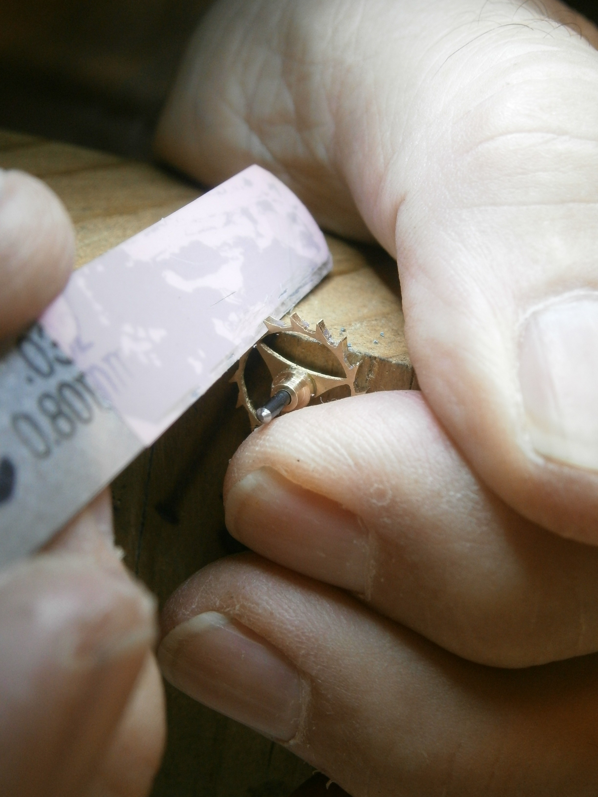
Figure 15: Polishing acting surface of tooth
The figure shows how I held the wheel, by now with its collet in place. In a block of wood that I could hold comfortably in my fist while it rested on the bench, I let in a piece of pivot steel and held the wheel stationary with an index finger, while polishing the faces under direct vision with a scrap of diamond-impregnated film glued to an old feeler blade. I went from 9 to 3 micron film and decided that was far enough.
Figure 17 shows the original wheel with a couple of trial wheels, with the one on the left nearly good enough, but as the rim at the top is a little irregular, I decided to finish with a spare one of the dozen or so that I had parted off at various stages of my trial. I had fitted this to the chronometer before I thought to photograph it, and as the chronometer has now run for over 24 hours with a gain of 1.7 seconds with an excellent action and the mainspring set up only two turns, I am not about to take it apart for a photograph. The final version is seen in Figure 15.

Figure 16: A compendium of escape wheels.
If you compare the finish of punched out edges, as shown in Figure 1 with the edges left by filing in Figure 15, there is surprisingly little difference (Figure 17).
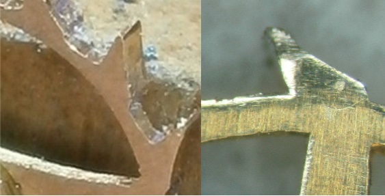
Figure 17: New (right) and old (right) wheel finish compared.
My teeth probably have more mass than the originals , but the rim is a little finer and the mass of the spokes is concentrated nearer the centre, so that the inertia, mr², of my wheel is probably about the same.
Making the collet was a simple turning operation, albeit at a small scale and industrial glues have made interference fits and riveting of collets unnecessary. Finally, Figure 17 shows a Soviet MX6 escape wheel being refitted to its arbor.

18: Fitting an escape wheel to its arbor.
I hope you enjoyed reading this post and if you haven’t already done so, I encourage you to buy my book, available from amazon.com. It may well tell you more than you wish to know about the structure of the marine chronometer.

Could I suggest that when you are crossing out the wheel with a piercing saw that your saw table has a slot in the middle just wider than your blade, then a hole in about half the distance from the blade to the saw back. This way you hold the saw pointing in one direction and move the work around.
I have just finished a contrate wheel for carriage clock, 60 tooth 12.2 mm dia with 5 crossings.
Traditionally piercing is done with a V slot but the smaller stuff is easier with a slot and small hole.
Thank you, Fergus. It’s an excellent idea.
Well done Mon AMI your patience and skills are admirable. John
From: The Mariner’s Chronometer To: john_black5@btinternet.com Sent: Tuesday, 6 February 2018, 3:44 Subject: [New post] 30: A new escape wheel for M21 chronometer #yiv6031500194 a:hover {color:red;}#yiv6031500194 a {text-decoration:none;color:#0088cc;}#yiv6031500194 a.yiv6031500194primaryactionlink:link, #yiv6031500194 a.yiv6031500194primaryactionlink:visited {background-color:#2585B2;color:#fff;}#yiv6031500194 a.yiv6031500194primaryactionlink:hover, #yiv6031500194 a.yiv6031500194primaryactionlink:active {background-color:#11729E;color:#fff;}#yiv6031500194 WordPress.com | engineernz posted: “I recently acquired a damaged chronometer that seemed to have been dropped on to a hard surface while out of its bowl, or perhaps the owner had thrown it at a wall in frustration. At any rate, the walls of the fusee track had been squashed in at one point” | |
Amazing job Dr Bill, as always. Keep coming here to read about your handy work and am never disappointed.
Best regards.
Pierre K.