This month, in search of a challenge, I bought a Soviet MX6 chronometer “for spares or repair”. It arrived, beautifully packed, a few days before Christmas. The previous owner had given an extensive list of problems and described them fairly. I thought I might have to replace or re-pivot the balance staff, as one photograph had shown the balance spring leaning to one side, but happily, the staff and its jewels had survived, though the spring was wrongly located in the upper spring stud. It was obvious from the amount of end play with the escape wheel that all was not well with at least one of its pivots, but this was as nothing compared to the state of the detent (Figure 1)
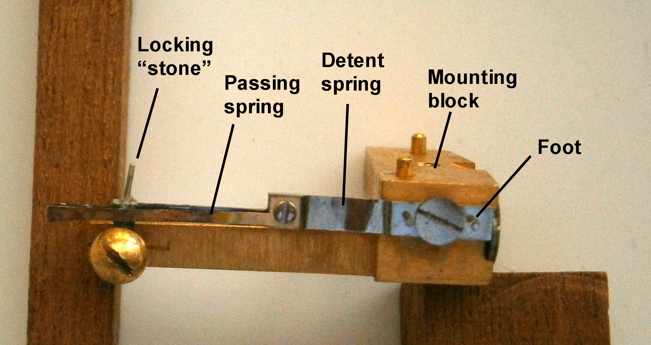
Figure 1: Damaged detent.
The detent spring was buckled and the locking stone had been replaced by a piece of steel wire. This led me to look more closely at the balance rollers and I found that the impulse roller too was a piece of steel, crudely shaped and glued into place like the locking stone. Stripping the instrument down completely, revealed that the upper escape wheel pivot was indeed broken, but the stub that remained had been utilised by replacing the hole stone with a tiny bronze bush crudely soldered on to the end stone bush.
I was able to salvage the end stone and I had a spare hole stone, so I made a muff to replace the missing pivot (see Post 7 of July, 2013) and all was well with the escape wheel. Interestingly, A L Rawlings in that fine book, “The Science of Clocks and Watches,” writes of having owned a chronometer which had gone for a hundred years from 1840 without showing any wear on the impulse face of a steel impulse roller, but since I had a spare jewelled impulse roller, I used it. By drawing the buckled detent spring repeatedly between my finger nails I was able to restore it to something like a functional shape, with no warping, and observed in passing that the passing spring was an original fitting.
That left the locking stone. A spare was available for US$ 85 with postage included, but that seemed a lot for a sliver of artificial ruby and, since I had once read of a clock that had been constructed with tungsten carbide pallets to its Graham dead beat escapement, I decided to see if I could make a locking stone from the same material. Tungsten carbide is an extremely dense and hard material, about twice as dense as steel and about as hard as ruby and sapphire. It can take a high polish and generally only tools using cubic boron nitride or diamond can be used to shape and polish it.
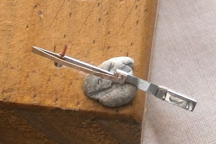
My blank was the stem of a solid carbide engraving cutter that I had bought as a job lot of worn cutters about ten years ago, to use as small lathe cutting tools, and I have a Quorn tool and cutter grinder that I constructed about 30 years ago, though it has had relatively little use. A little improvisation to allow the blank to be rotated against the face of a 400 grit diamond grinding wheel resulted in the set up shown in Figure 2.

Figure 2: Grinding set-up.
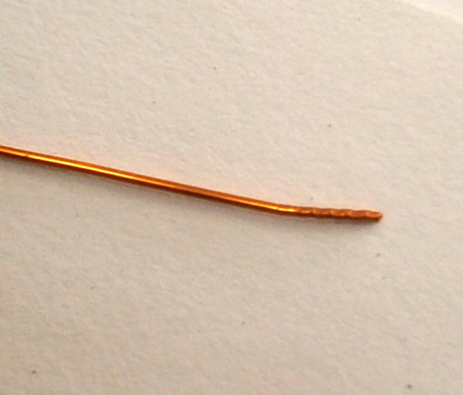
The blank is set up with its axis parallel to the face of the wheel and I fitted a handle to the graduated disc on the left so that I could rotate the blank against the rotation of the wheel. The Quorn has a micrometer feed that allows very small increments to be removed, so eventually I achieved a cylinder of tungsten carbide a mere 0.8 mm in diameter. Then, by locking the tool against rotation I ground a flat about 2 mm long to form the locking face, rotated the blank a further 110 degrees to give clearance behind the locking face and to allow about 12 degrees of draw as well. Cutting off was as simple as using the corner of the wheel to grind a notch and then breaking it off (Figure 3)

Figure 3: Cutting off.
The finish left by a 400 grit wheel, although fine by normal standards, won’t do for clock work and has to be lapped and polished. I did this by hand, holding the cylindrical part in a pin vice with just the flat part projecting and resting it on a piece of metal of a thickness such that the handle of the vice lay on the table while the part with the flat was supported by the metal. (Figure 4).

Figure 4: Supporting the work piece.
Any tendency for the lap to dip or rock resulted in it fouling the metal, so it was easy to maintain the orientation of the lap, shown in use in Figure 5.

Figure 5: Lap in use.
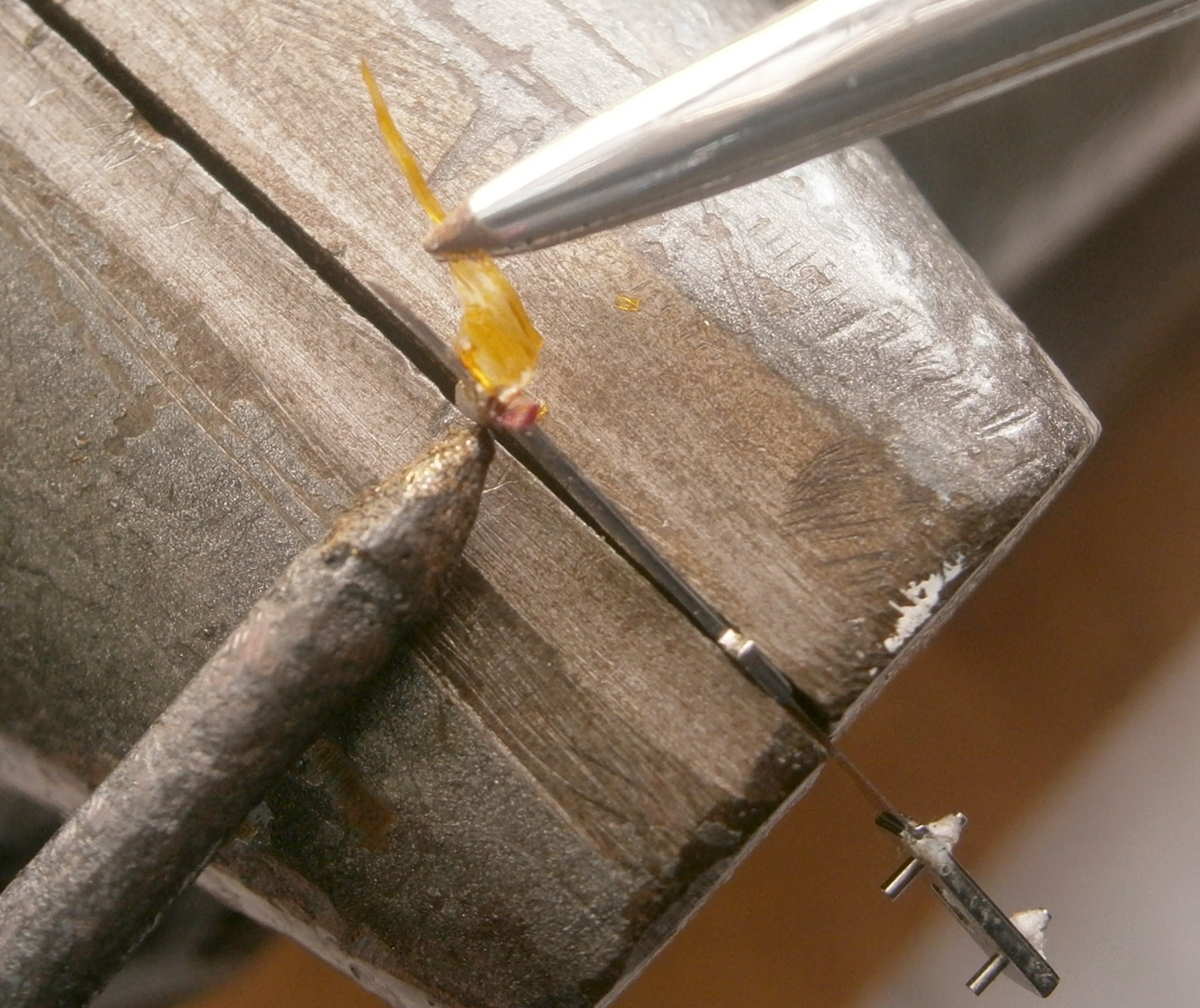
By using progressively finer grades of lap impregnated with diamond grit, 20 microns, 10 microns, 5 microns and finally 1 micron, I has able to give the acting face a high polish. Figure 6 shows the finished locking stone, cemented in place in the detent with 8 to 12 degrees of “draw”.

Figure 7: Finished locking stone in place.
The “proof of the pudding is in the eating” of course. I had to adjust the depth of engagement of the locking stone with the escape wheel teeth and refit the balance spring in the upper spring stud and after a general overhaul as described in my book “The Mariner’s Chronometer“, the timepiece began easily when wound. I found it necessary to tweak the discharge roller a little to achieve a satisfactory action and it is at the moment gaining at an unacceptable rate, but the new locking stone is plainly doing its job. Perhaps the balance spring is a little too short, or I could perhaps replace the timing weights (Post 21: of April 2016, A Balancing Act). The holiday period is still young…
28 December 2016: The balance spring was indeed a little too short, but increasing it tended to capsize the spring, and there was not enough room to wind out the timing weights to correct the error of about 2 minutes a day, so today I made two sleeves, each weighing 80 milligrams, to fit over the weights (see Post 21). Now the error is within a “tweakable” range.of about 24 seconds/24h.


Recent Comments