Note that all illustrations in the blog may be enlarged by clicking on them; and reading of the text may be resumed by clicking on the Back arrow (top left)
I have described in “Getting started” how to remove wedges from the balance of a chronometer of standard design and at first the Hamilton watch company immobilised the balance for transport the same way. By the time that the official Manual for Overhaul, Repair and Handling” of the Hamilton Model 21 chronometer was published in 1948, a new method of immobilising the balance was being fitted to chronometers by the US Navy, as the chronometers became due for overhaul or repair. This locking arm is shown in Figure 1.

Figure 1: Balance locking arm
To lock the balance the locking screw is loosened and the locking arm swung until the hole in it traps a large timing nut on the balance rim, when the screw is re-tightened. Unlocking is the reverse of locking. Although this places the balance and its pivots at less risk than when inserting wedges it was still possible for the ham handed to cause damage, and it was still necessary to remove the instrument from its gimbals and open the case. At some time after 1948, a balance locking fork was fitted as chronometers were overhauled, allowing the balance to be unlocked without opening the case. If on inverting the chronometer a small hole in addition to the winding hole is present in the dust cover, a fork is probably fitted, provided the movement is in its own case. Figure 2 shows the hole and on rotating the cover, the socket of an Allen screw is revealed, before the winding square comes into view in its own hole

Figure 2: Locking balance
If the original key is absent, any 1/16th inch AF (across flats) Allen key will do to loosen or tighten the screw and, as the screw is captive, you need not fear that you will over-tighten it and damage the movement or unscrew it completely so that it gets lost in the works. Figure 3 shows the fork itself. There are two soft plastic pads on the ends of the arms and when the screw is tightened against the springy stem, the pads bear on the balance rim and bring it to a halt.
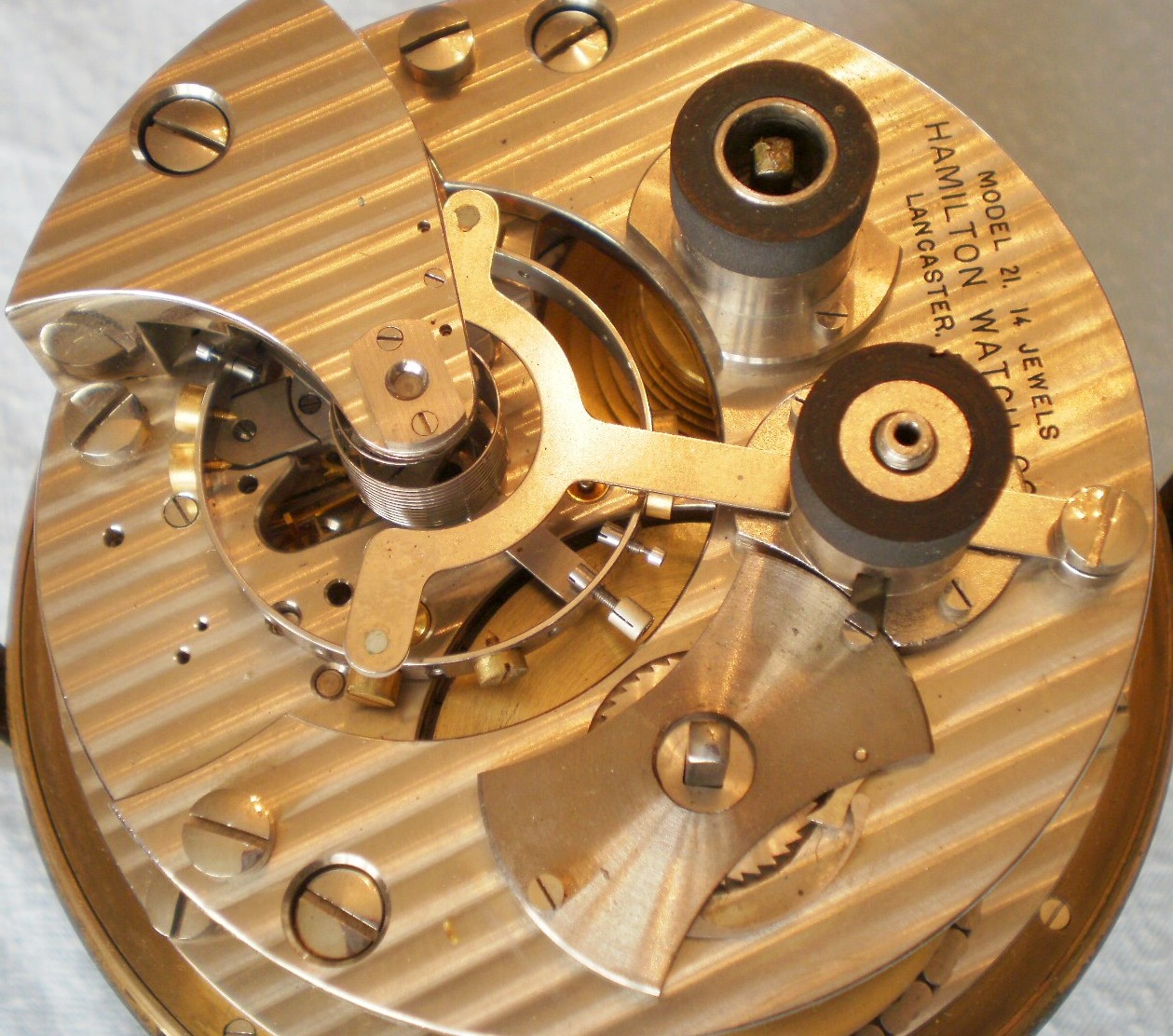
Figure 3: The locking fork.
When servicing a Hamilton Model 21 chronometer, the fork and the bridge that straddles it have to be removed before the upper balance cock and balance can be removed. As Figure 4 shows, the bridge is attached to the plate by two screws, while the fork itself is secured with a single screw. Once the bridge has been removed, the fork is supported with tweezers while its attaching screw is removed.
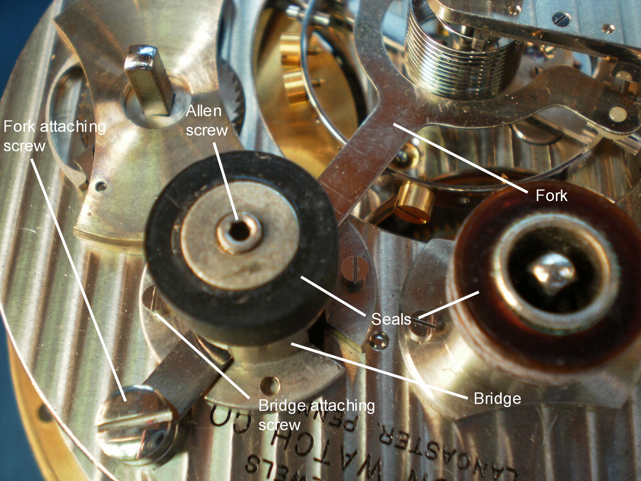
Figure 4: Attachment of the locking mechanism
By 1970, 13,086 Model 21 Chronometers had been produced, about 11,000 of them for the US Navy, the US Maritime Commission and the US Air Force during WWII. The majority of the ones I have seen are fitted with the locking fork.

Recent Comments