39: A Late Thomas Mercer Chronometer.

3 10 2020

Some months ago I bought a non-working Mercer chronometer on a local auction site, but was unable to collect it because of Covid 19 lock-down. The seller was unwilling to post it, even at my own risk and with careful packing instructions. He had fairly guessed that the upper balance pivot was broken.

Thanks to a visiting friend, the chronometer eventually arrived in its original carrying case and with its original Mercer certificate of goodness. Its mean daily rate at 21 Celsius over three days of December, 1973 was given as 0.3 seconds, losing. It had also been tested at 4 and 35 degrees, with differences of daily rate between any two temperatures not to exceed 1.5 seconds. If allowed to run for 48 hours without winding, its daily rate was not to exceed 2 seconds.

Cases

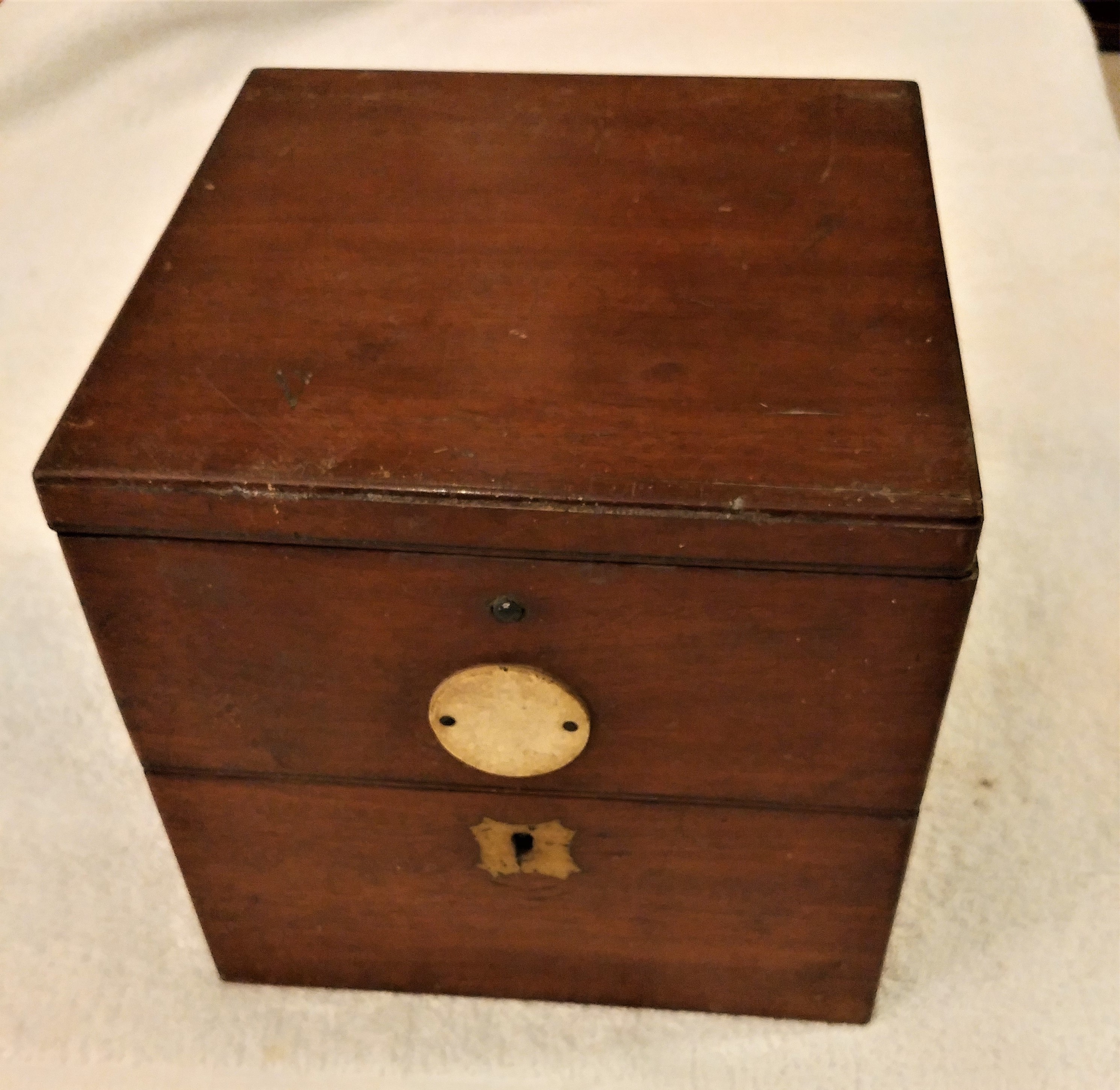
Figure 1 shows the outer case as received and the inner case after restoration. The outer case is of 10 mm mahogany-faced plywood with rebated corner joints and lined with green baize-covered padding. The inner case is of solid mahogany with a traditional design, though without a lid or handles. Both had been coated with a thick layer of dark brown varnish that took a good deal of effort to remove. Hinges and catches are of chromed steel.

Figure 1: Cases

Gimbals

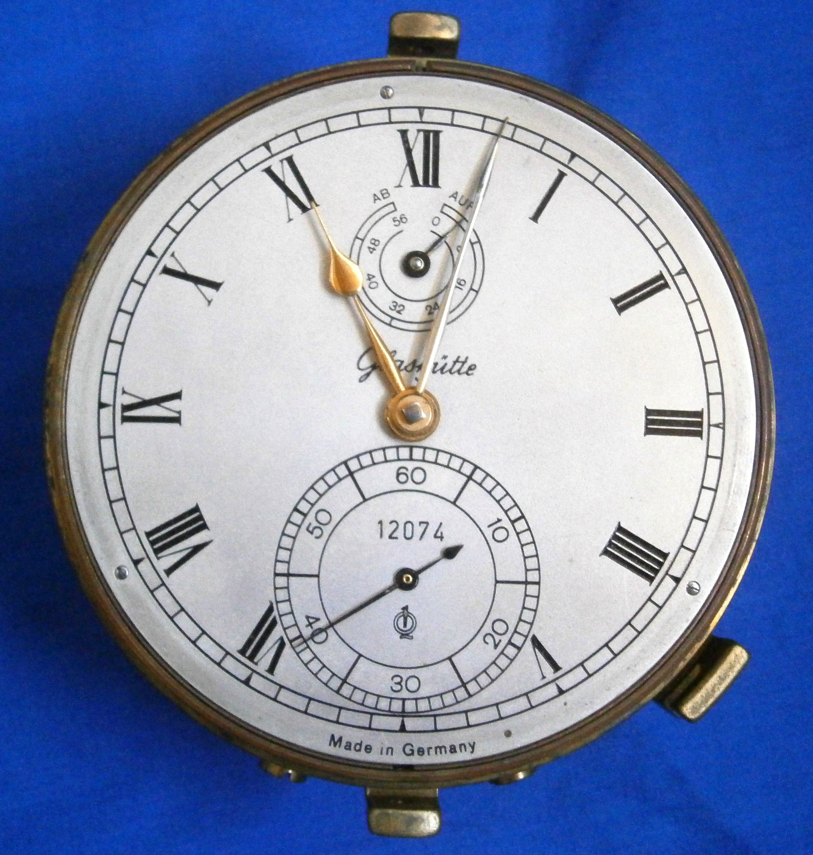
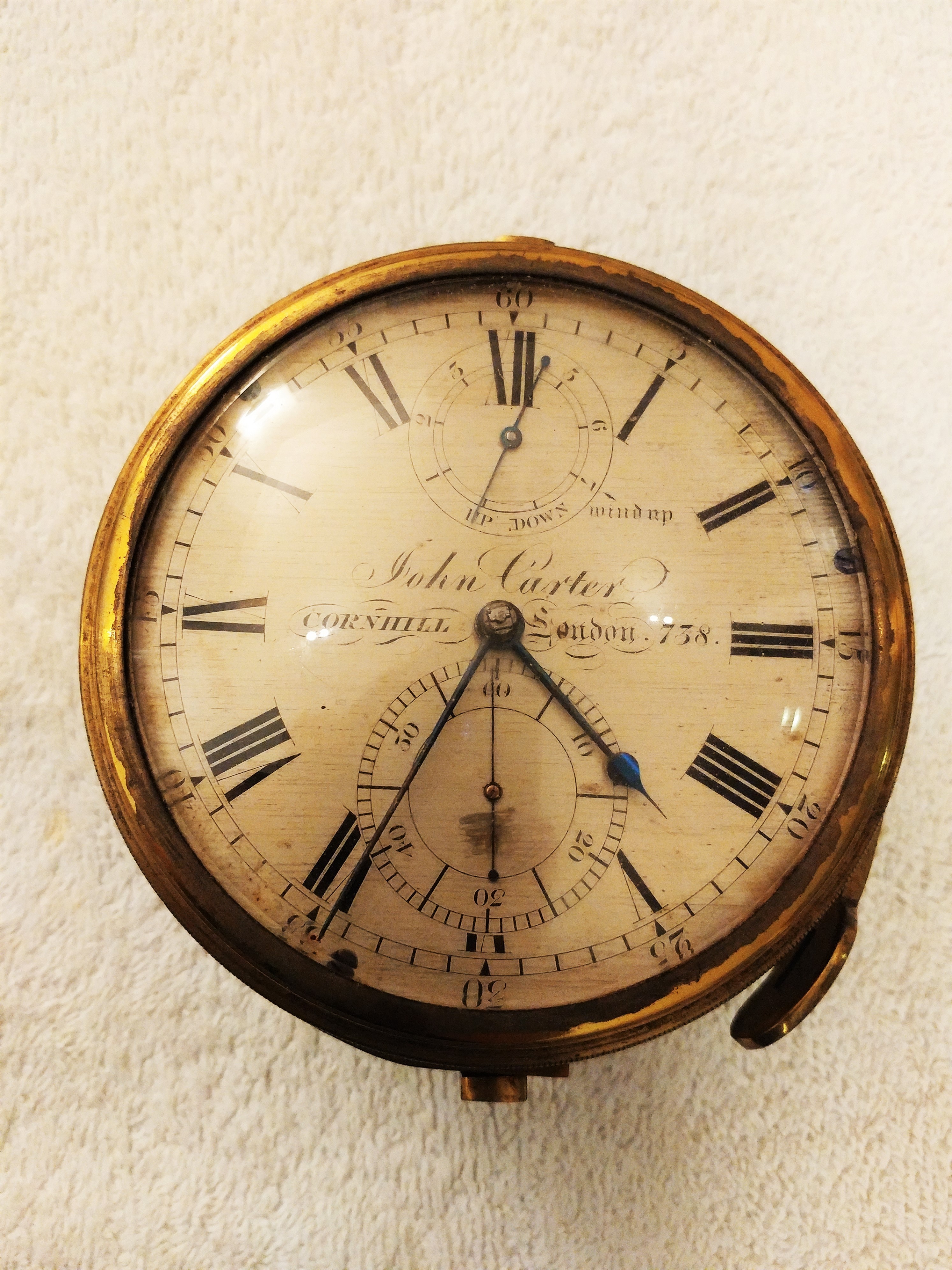
Figure 2 shows the view upon opening the inner case. The face and bowl are of normal design, the numerals are Arabic and the hands differ little from those of a hundred years previously. The supports of the bowl and gimbals in the case are a little unusual and are shown in Figure 3.

Figure 2: General view in case

Figure 3: Support of bowl in gimbals ring

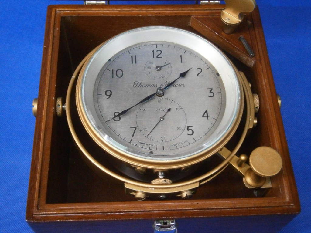
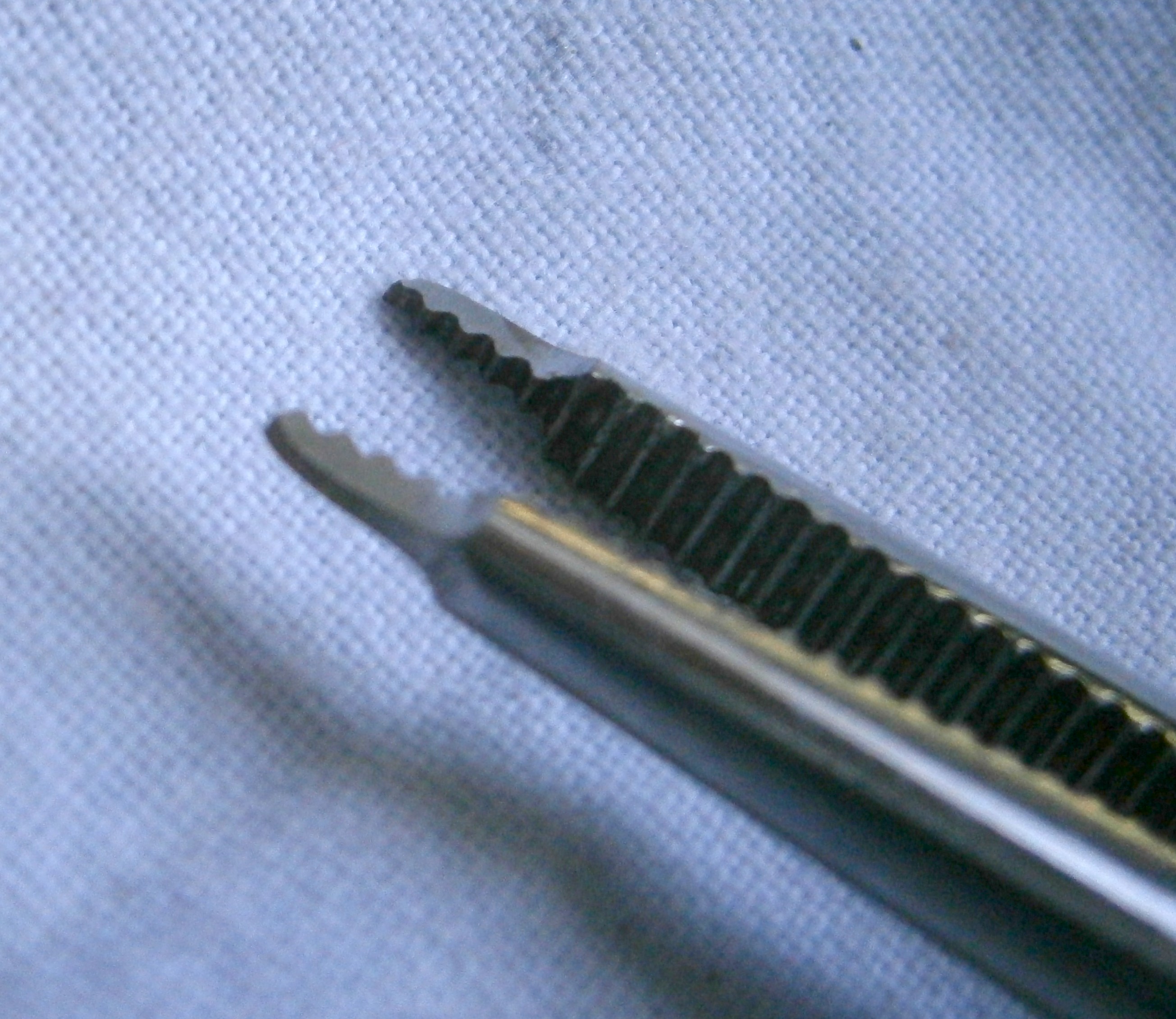
Instead of a dome or cheese head screw, an Allen screw is used, locked to the ring by a capstan nut with diamond knurling. The reduced tip of the screw enters a boss in the bowl bracket. The ring itself is usually supported in the case by  screws through the wood of the case, locked by a large and thin finger nut with straight knurling. A chronometer in its bowl weighs about 2 kilograms (4.4 lbs) and if carelessly “handled” by a postal service, may well tear out of the wooden sides of the cases.

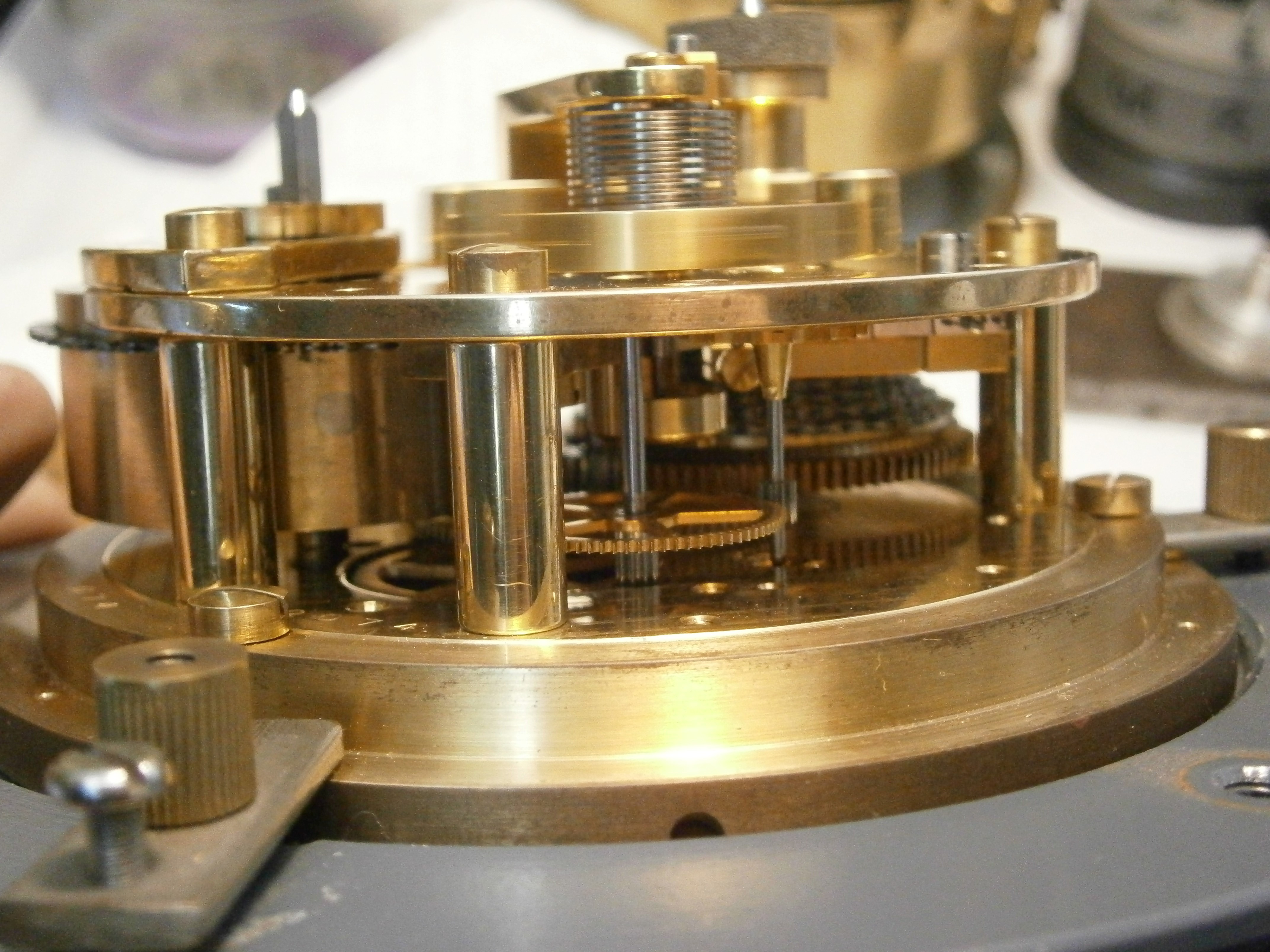
Figure 4 shows how Mercer has moved on from tradition and has adopted an engineering approach by screwing large diameter threaded bushes through the side walls for the Allen screws that secure the gimbals ring.  However, unless it is being transported by hand, it is always wise to remove the chronometer in its gimbals and sit it on resilient padding on the bottom of the case, surrounded by more padding and with more on top. It is also a sound plan to add some stout card or thin plywood on top of this padding  inside, to protect the glass of the lid from any movement of the chronometer.

Figure 4: Bush in side wall of case.

Face

As might be expected of an instrument that showed no signs of ever having been overhauled, it face looked a bit shabby, but this was easily improved by cleaning, lightly abrading down to the brass with 1200 grit emery paper and re-silvering using a proprietary preparation. None of the engraving needed to be refilled.

Figure 5: Face before and after re-silvering.

Movement

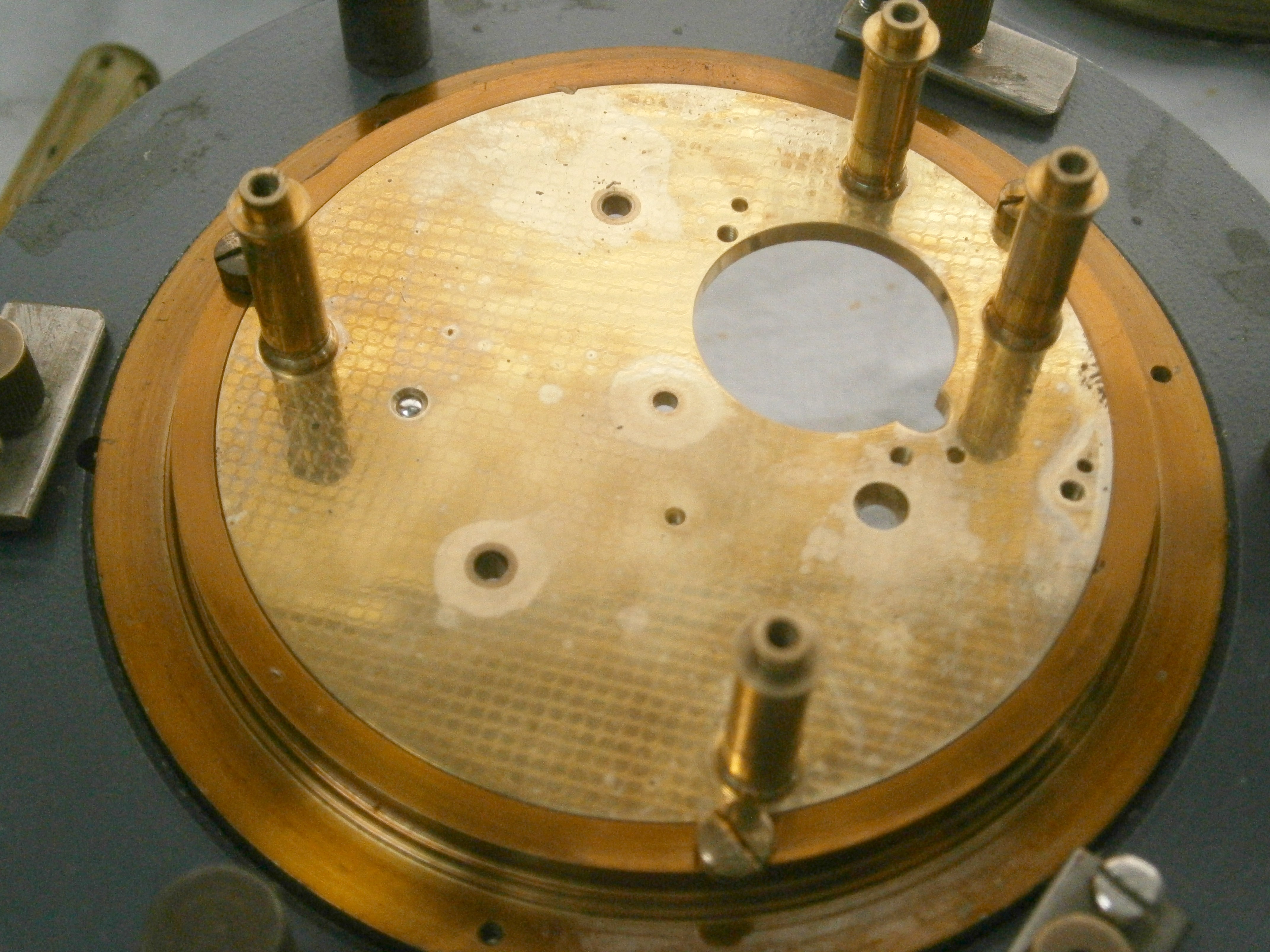
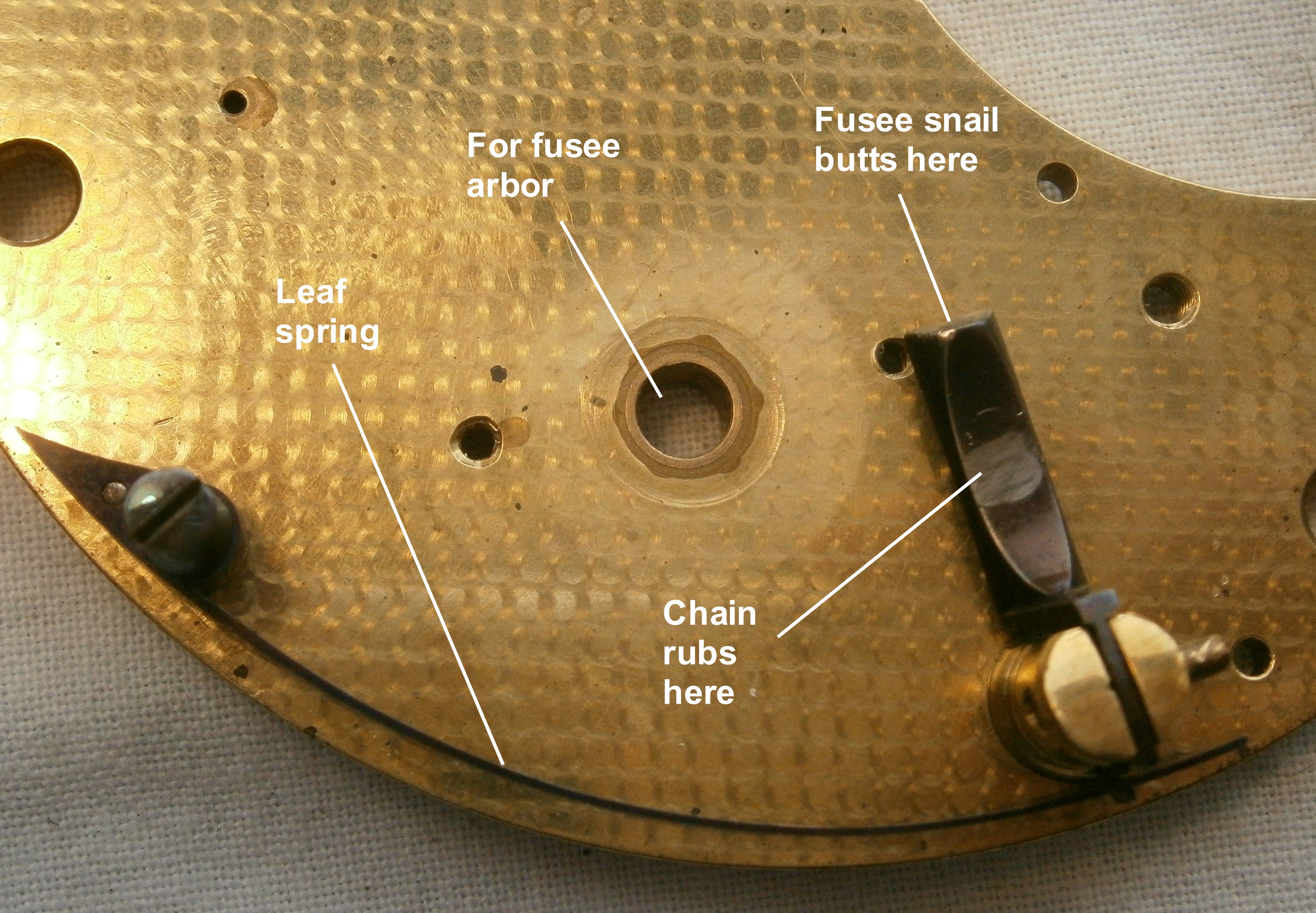
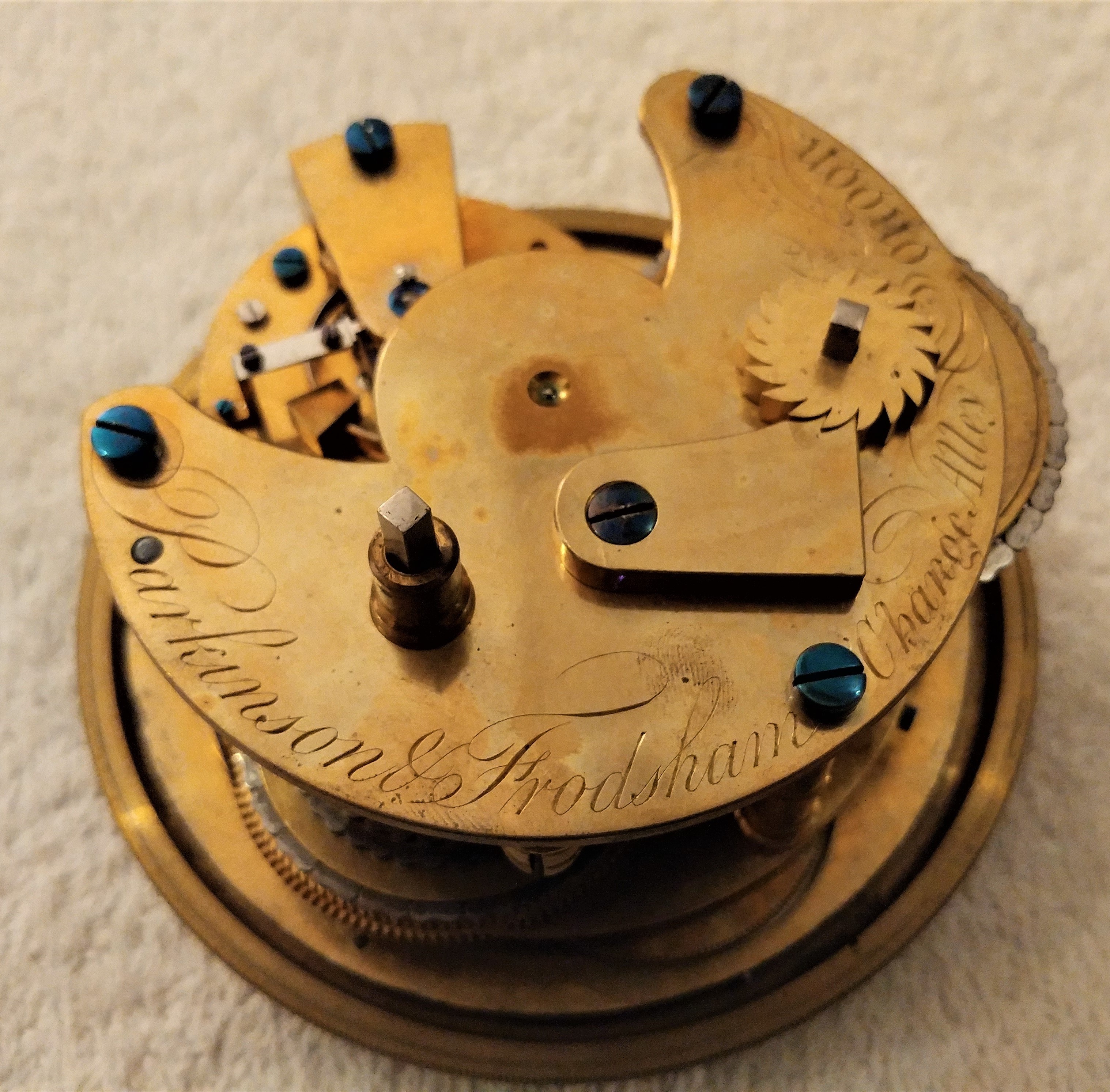
Over many years, oil and grease in the chronometer mechanism gradually evaporates from where it has been placed and diffuses throughout the mechanism and bowl interior to condense and leave a thin oily film (this also happens with binoculars). Figure 6 shows the generally dingy condition of the top plate and upper balance cock. The spring barrel has been protected in part by the barrel plate and shows some of the original finish. The underside of the plate showed similar areas where the spring barrel and fusee had protected the plate finish.

Figure 6: Top plate as received.

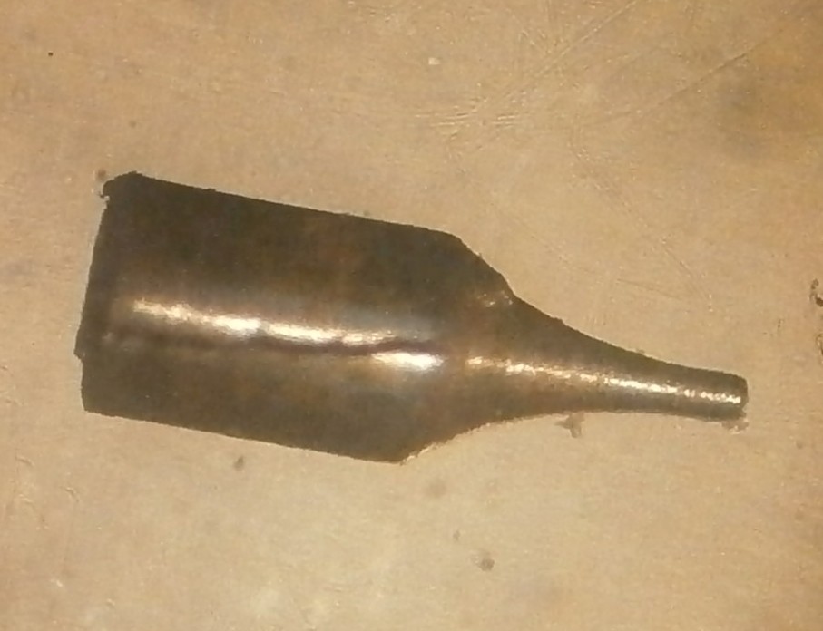
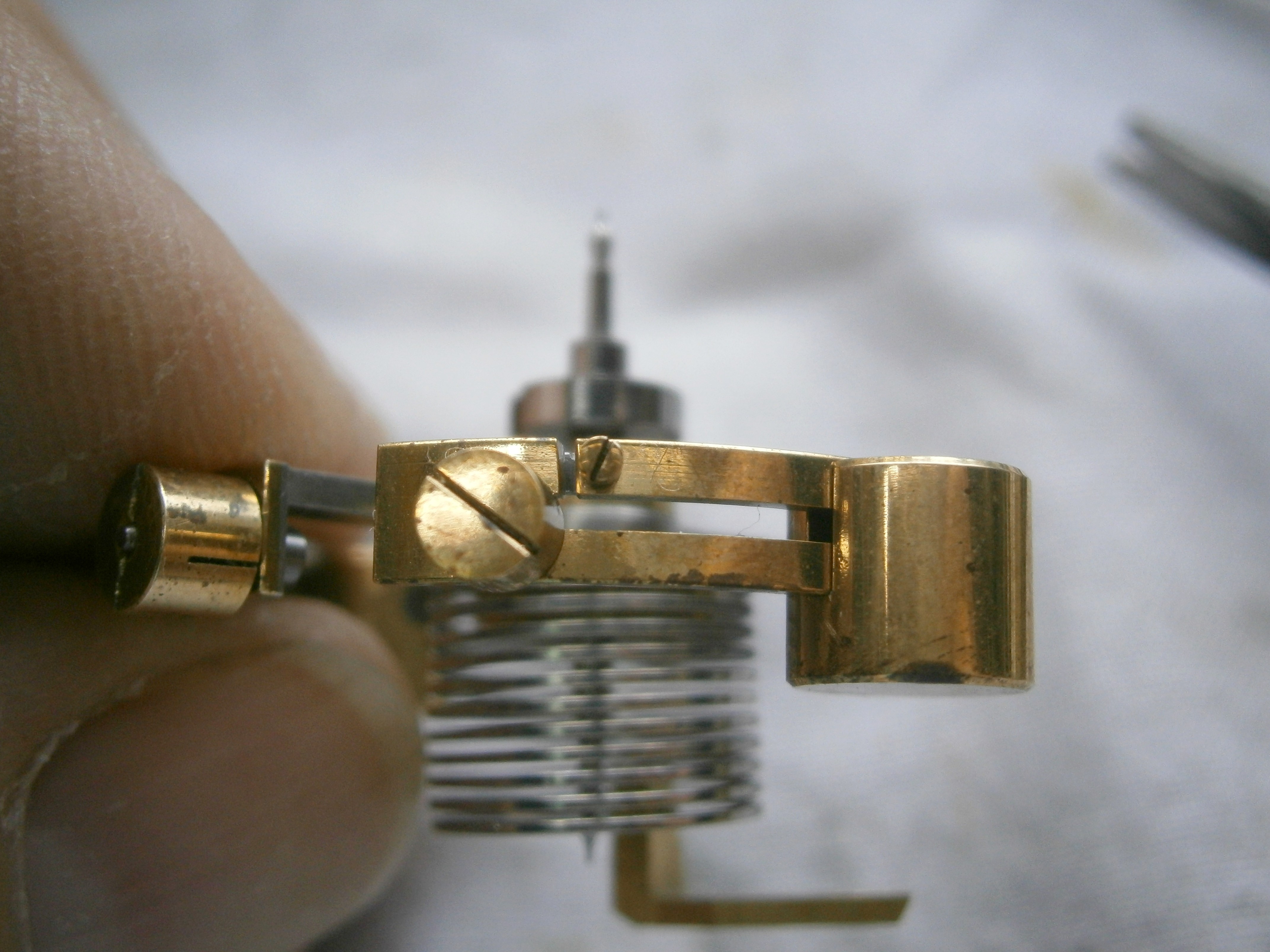
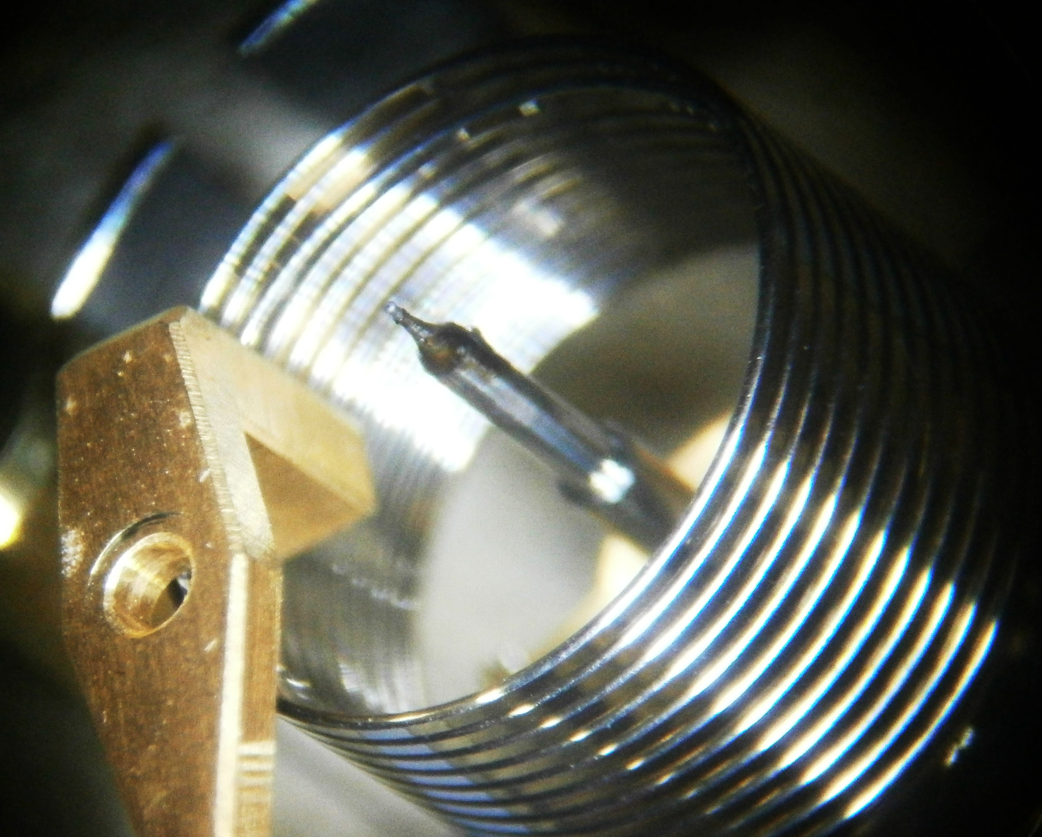
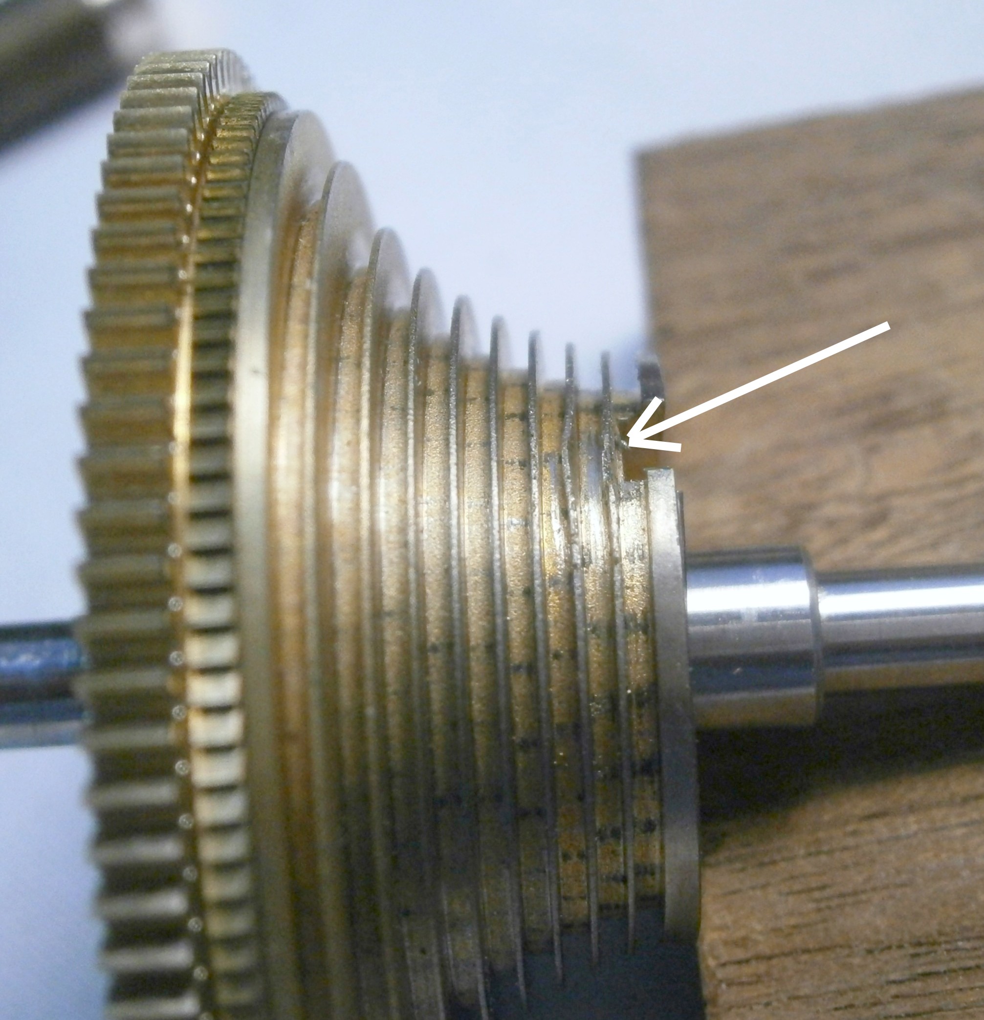
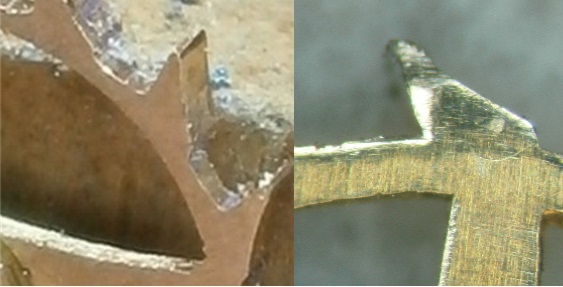
The seller had correctly suggested that one of the balance pivots was broken, and after fully stripping down and cleaning the chronometer I replaced the broken upper pivot with a muff (see Post number 7, part 2, 27 July 2013). This of course also involved removing the balance wheel, its hub and the two rollers. The procedure led to a series of misfortunes, beginning with making the muff too tight a fit on the turned down balance staff. With a wall thickness of only 0.1 mm, a crack developed unnoticed in the muff and under load it propagated with the result shown in Figure 7.

A disaster to the detent

Figure 7: Cracked muff.

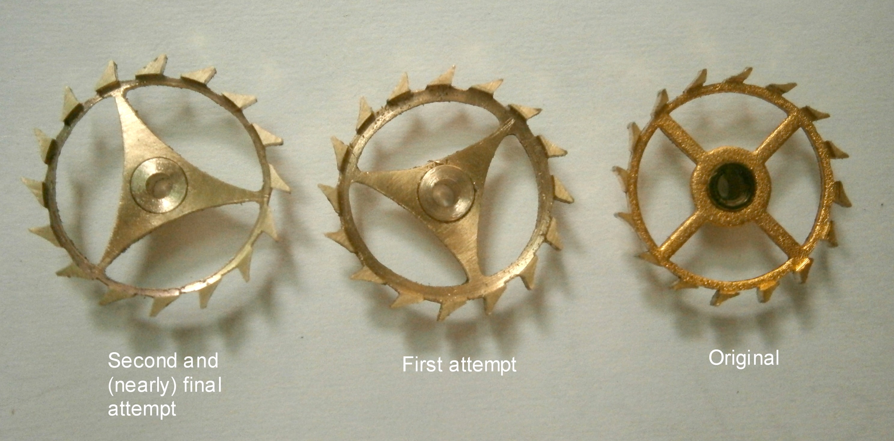
.When I came to regulate the chronometer, I found that it varied so widely that I knew something was amiss and I first looked at the balance staff. In this blog and in my book “The Mariner’s Chronometer” I have repeatedly emphasised that one should always block the third wheel before removing the balance or detent. On this occasion, after several tries of a new muff for length, I forgot. I then inadvertently knocked the locking stone off an escape wheel tooth and the chronometer “ran away.”  I got a finger on the third wheel, but not before the locking stone (or “jewel”) was badly chipped, the detent spring buckled and an escape wheel pivot was broken.

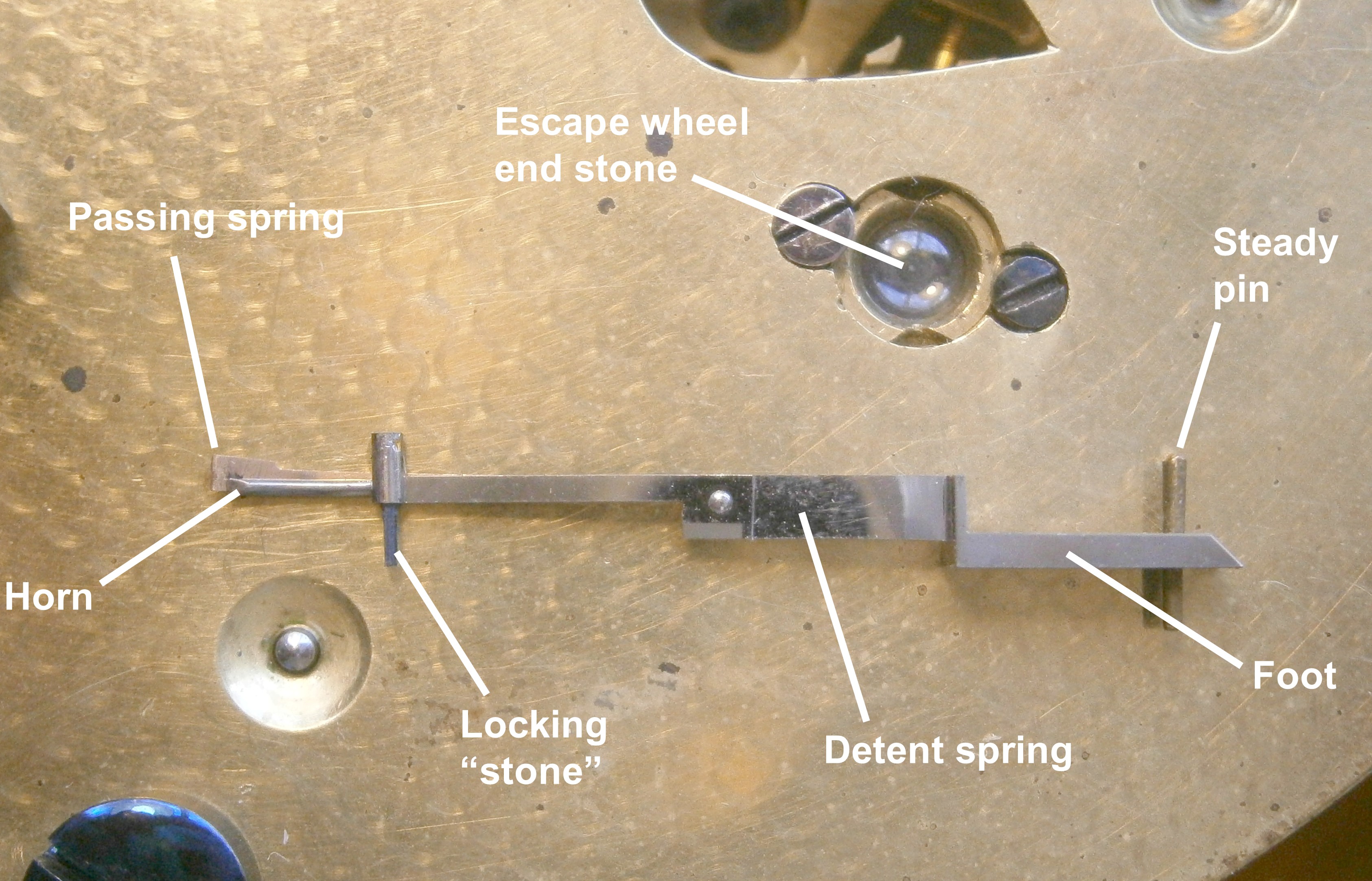
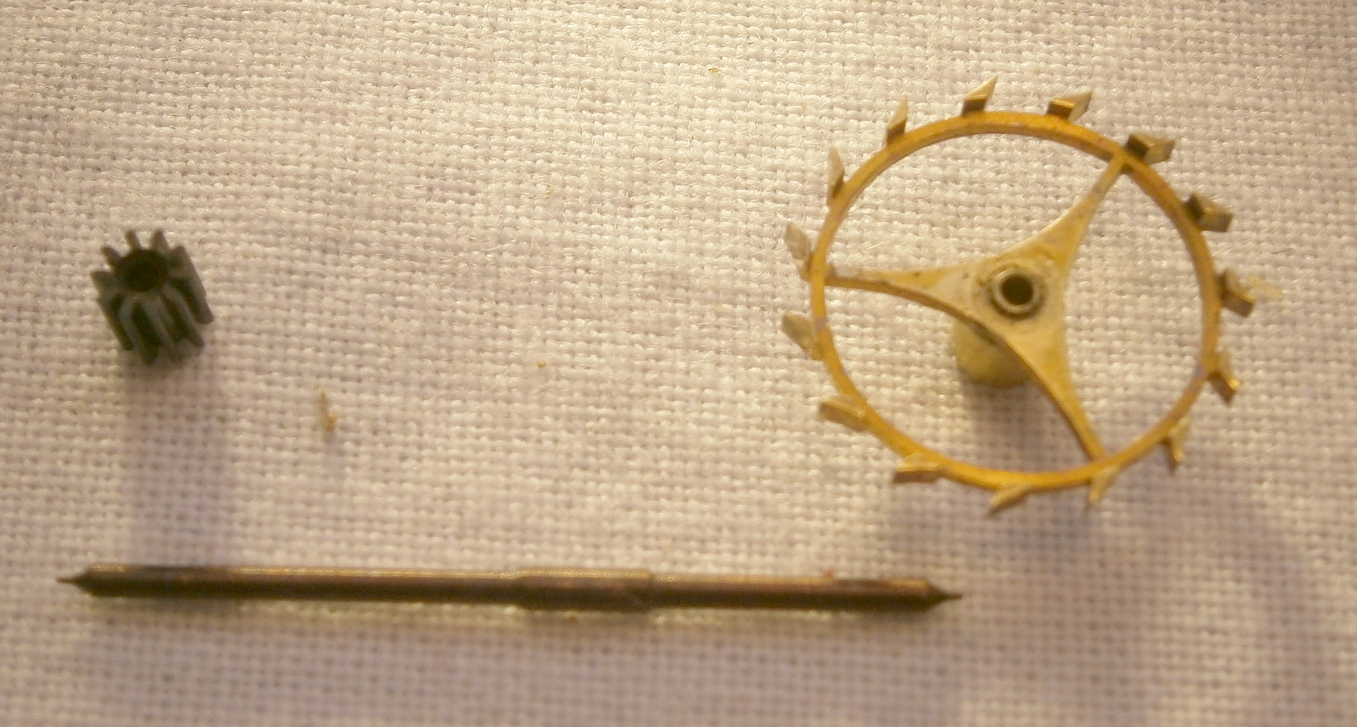
Mercers of St Albans still exists, though they no longer make chronometers. I hoped that they might nevertheless have kept spare jewels, but I was out of luck and so had to make my own replacement. Figure 8 shows the undamaged detent.

Figure 8: Detent and support block.

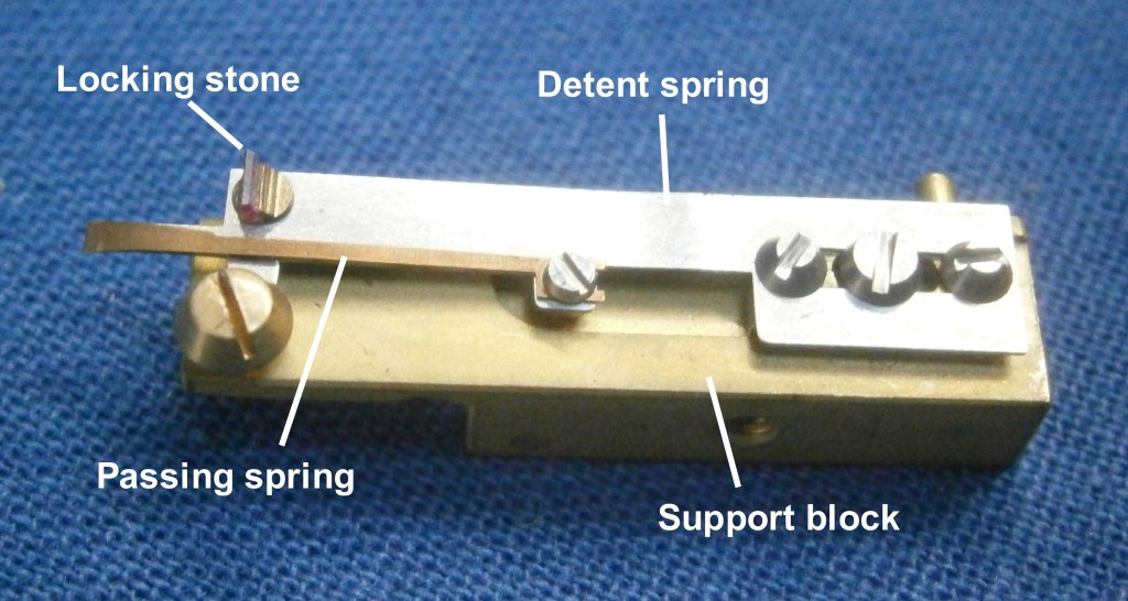
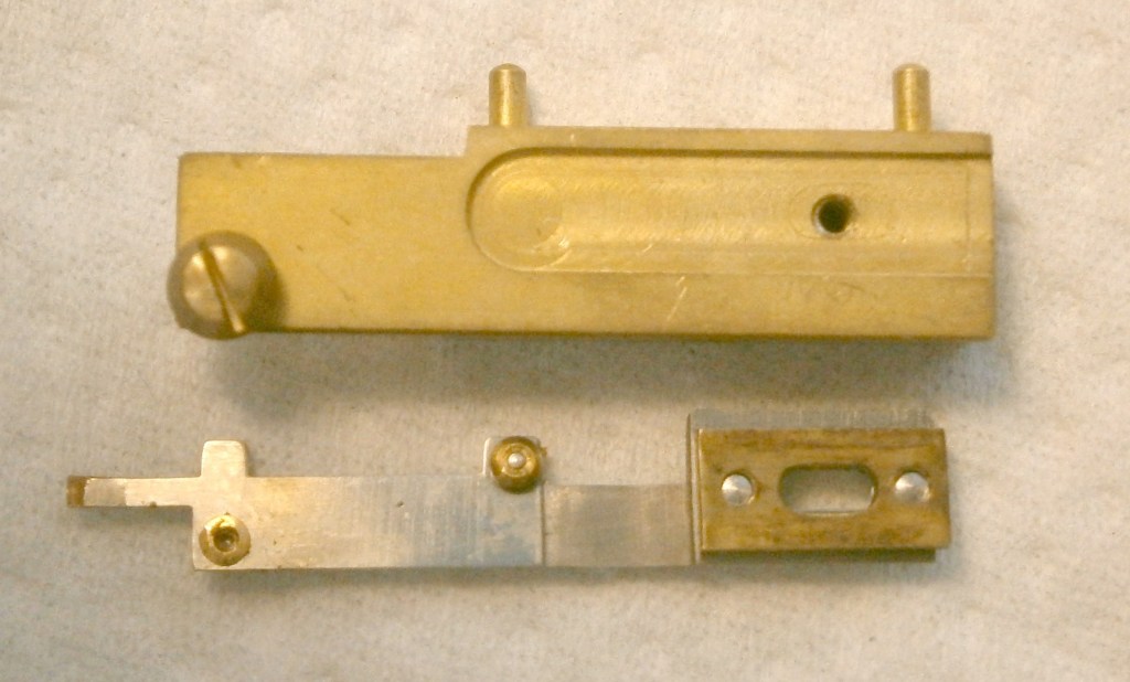
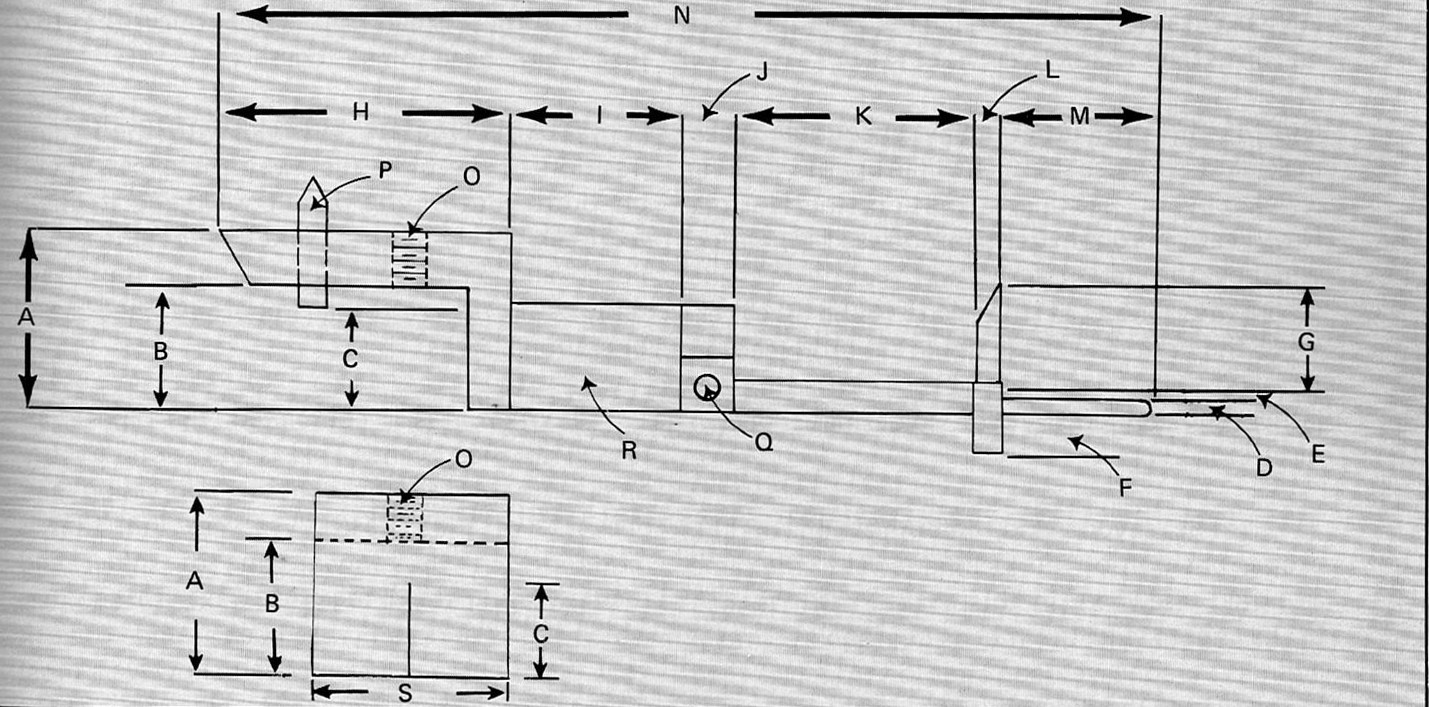
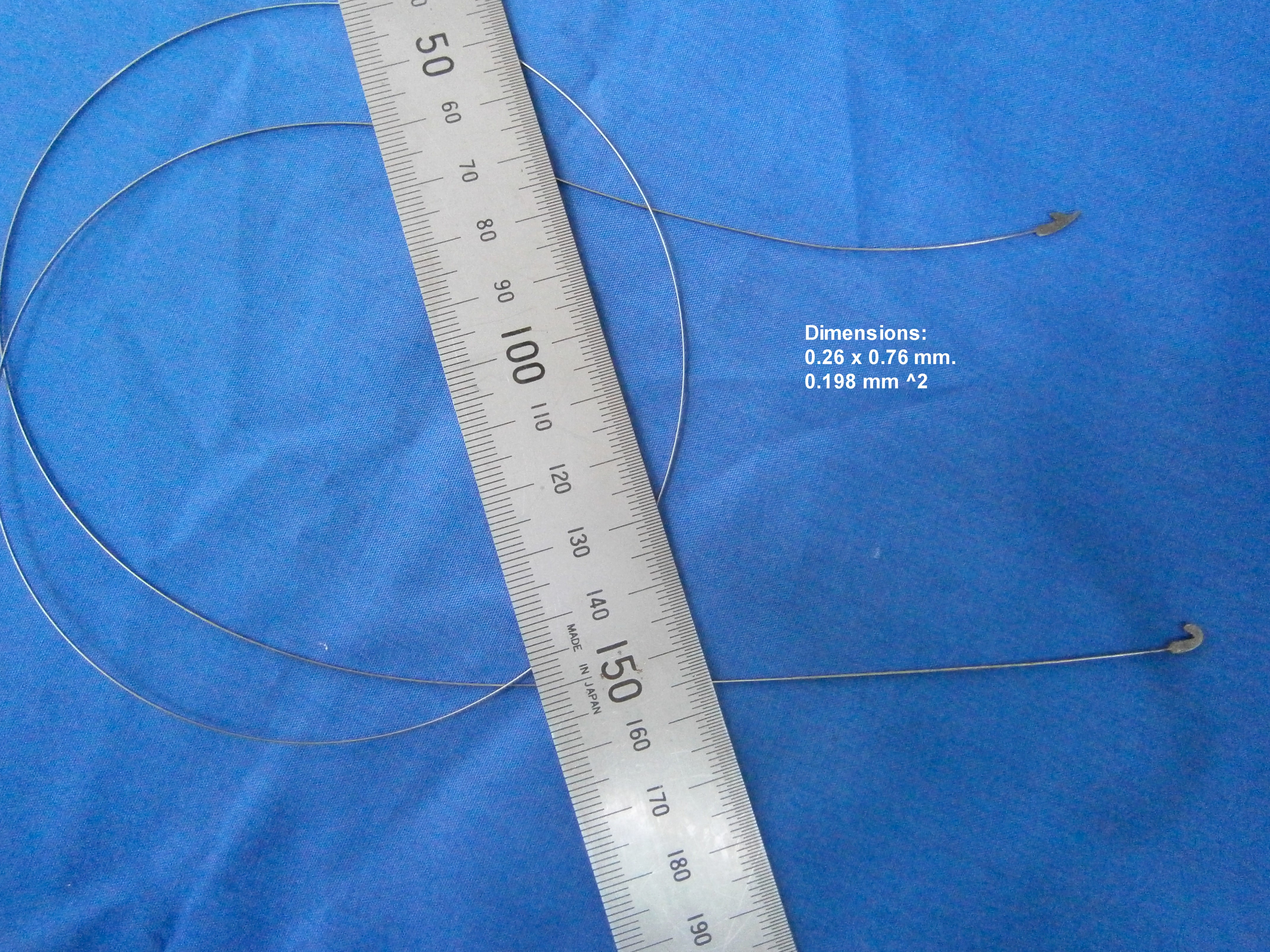
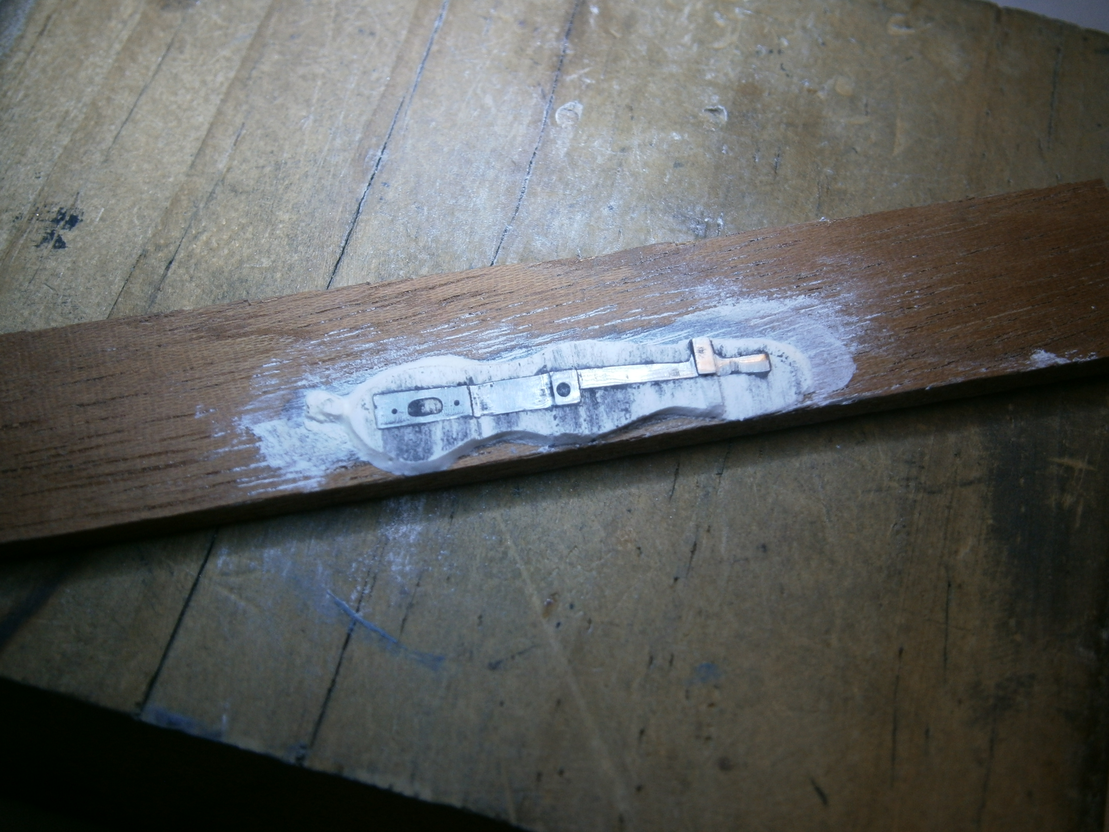
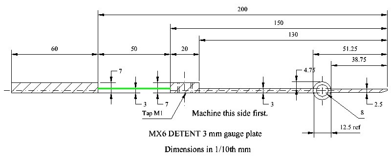
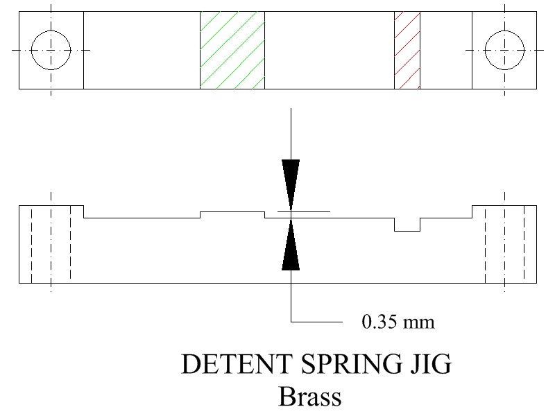
The usual form of detent has a narrow ruby locking stone of about 0.8 mm x 3 mm that projects above the line of the detent spring. As well as being delicate, it also imparts a twisting force to the spring. From about 1946, Mercer arranged for the stone to be a chip of ruby of low profile, held inclined towards the tip of the detent in a brass holder. Both the stone and the horn of the detent are aligned with the detent spring. The detent itself was a stamped-out strip of white metal about 0.3 mm thick with the detent spring ground down to about 0.08 mm thick. This was then attached to a narrow strip of brass by two screws, the whole sliding in a groove machined in the support block. Figure 9 may make this clearer. Note how the holder for the locking stone and a brass bush for the screw that holds the passing spring are swaged on the underside of the detent.

Figure 9: Underside of detent.

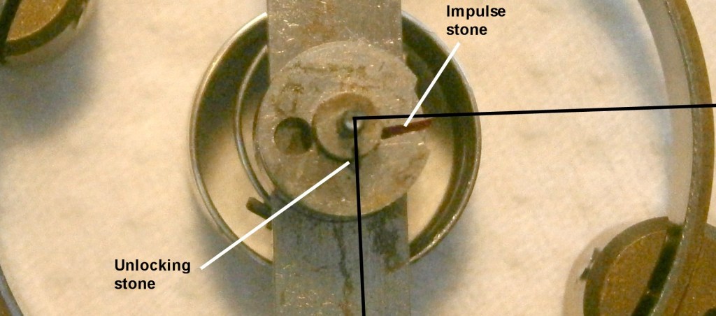
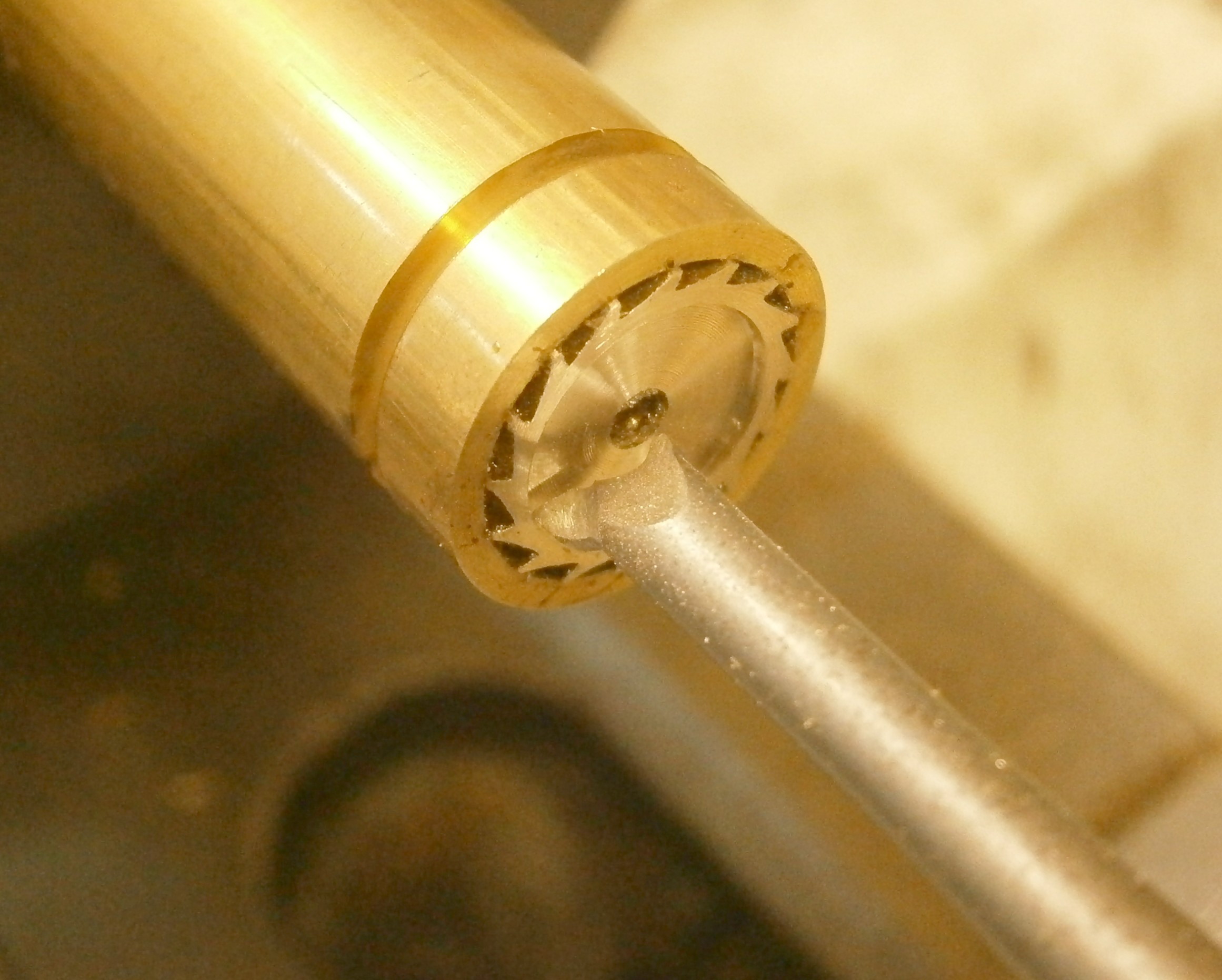
Usually, one of the first things I do upon removing a balance for the first time is to take a photo of the impulse and unlocking rollers for reference, so that I can replace them in approximately the same orientation when re-assembling. Somewhat unusually in this instance is that the impulse stone is not radial, while the unlocking stone is as usual (Figure 10).  The angle between them, at least through their tips, appears to be about 90 degrees, rather than the more usual 80 degrees or so.

Figure 10: Rollers and stones.

When replacing escapement pivots it is important that there should be the very minimum of end play, consistent with free rotation, as not much more than the end 0.1 mm of a pivot is actually engaged in the hole stone. If a pivot is missing, then the original length of an arbor is unknown. I usually turn down the arbor for a little longer than needed and make the hole in the muff a little deeper too, so that the overall length can be adjusted by using a small soldering iron to soften the shellac that holds the muff in place,. Nevertheless, I had to make several muffs of slightly different lengths before finding one that would allow a perfect fit. A balance staff or escape wheel arbor that is just a little too short may lead to occasional and mysterious tripping, in which the instrument suddenly gains half a second. No amount of varying the angle between unlocking and impulse stones fixes the problem.

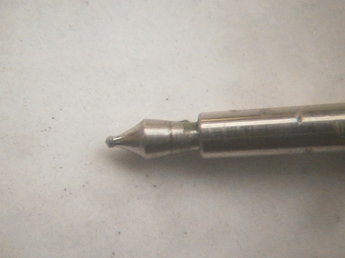
The detent I suspect is made of nickel silver, a bronze in which about half the zinc has been replaced by nickel, as it was relatively easy to straighten the buckling by drawing it between the tips of a pair of tweezers until it appeared perfectly straight. The locking stone was another matter, as it had slipped from my tweezers, to be swallowed up by some ruby-hungry entity lurking at the back of my bench. After remarking to myself that this was very unfortunate and failing after a lengthy search and tidy-up to find it, I had to make a new one from tungsten carbide Figure 11.

Figure 11: Tungsten carbide locking stone

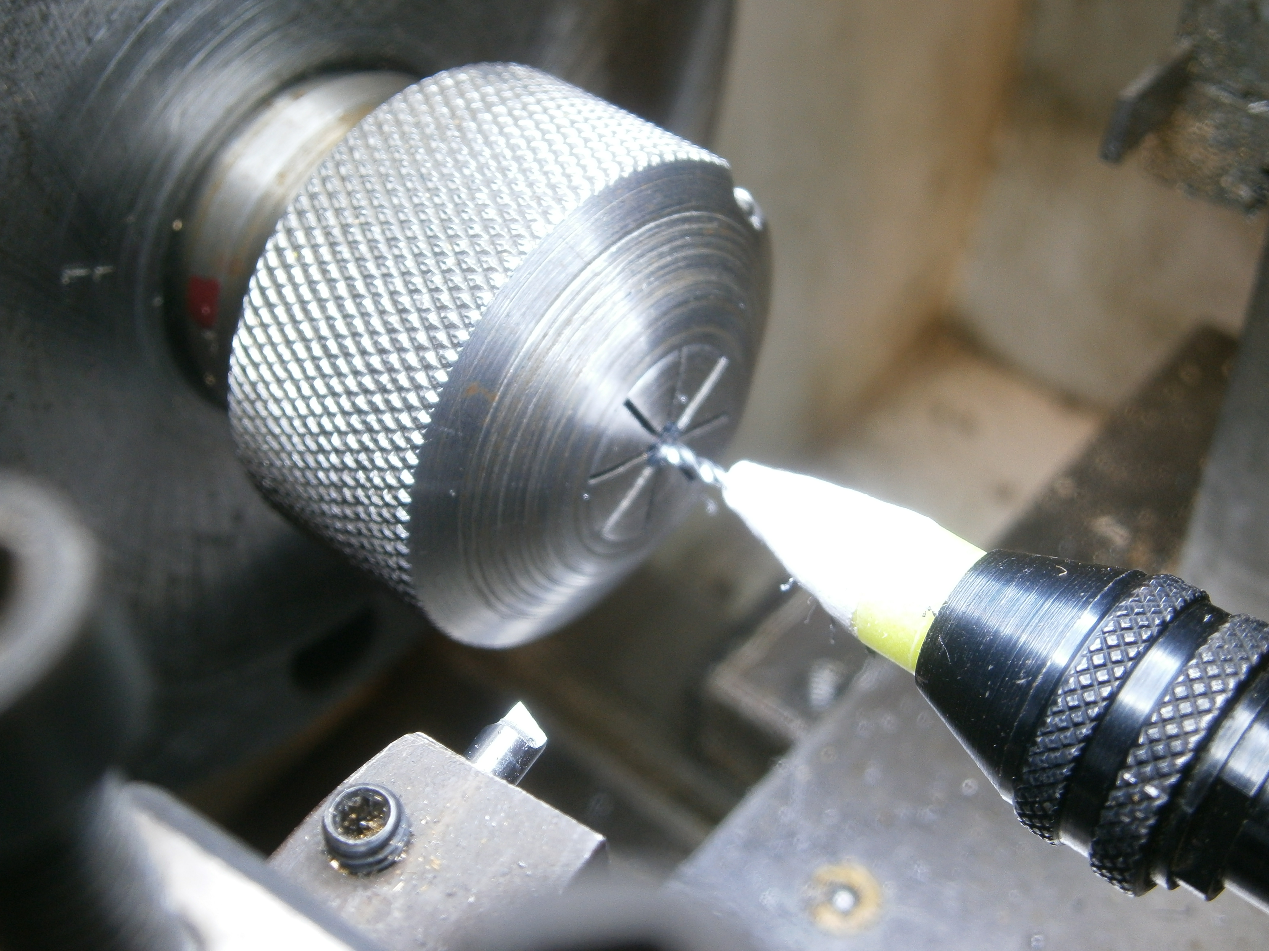
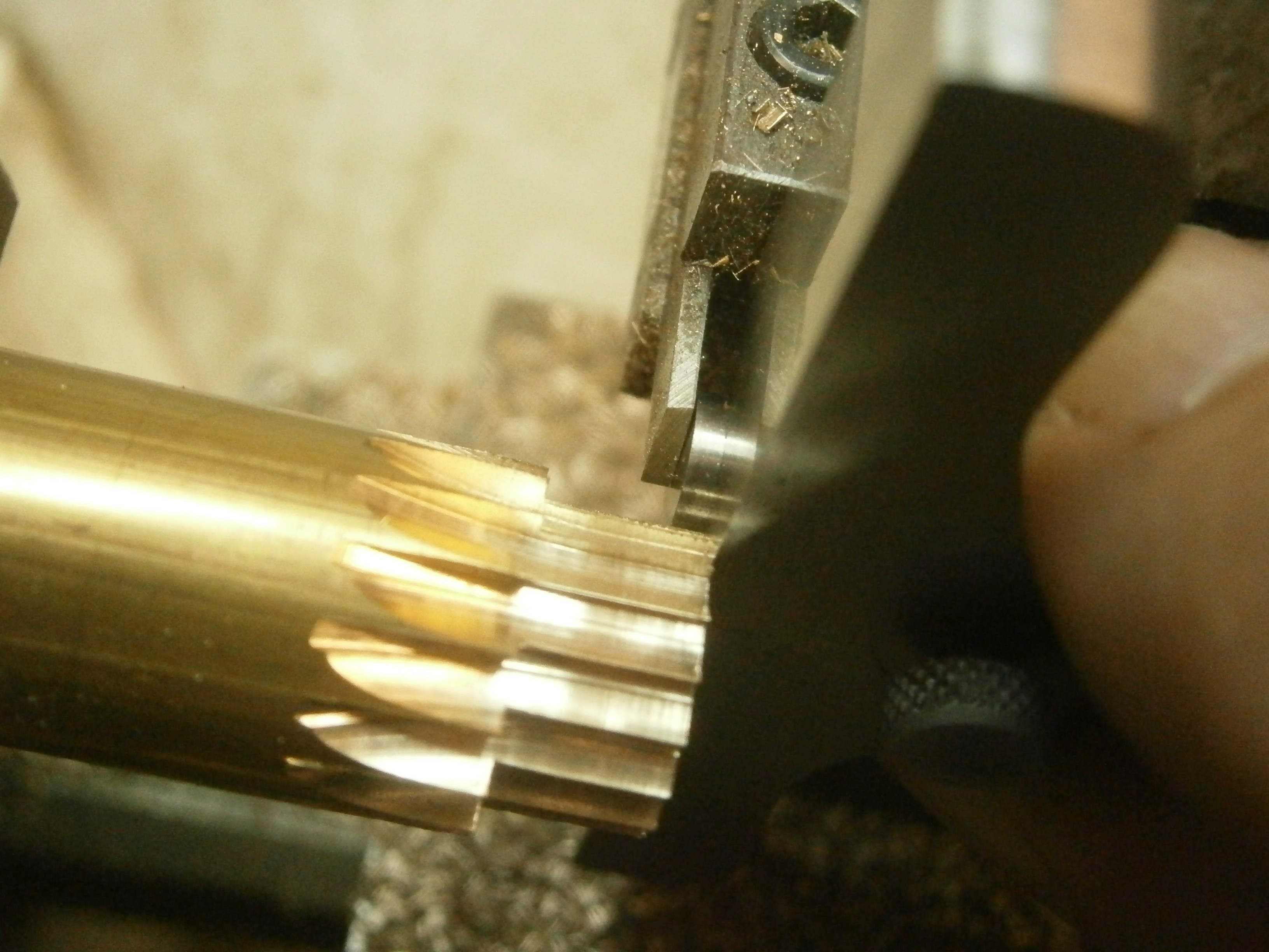
The stone is a mere 0.3 mm thick and 1.6 mm square so for someone like me, unused to handling such tiny pieces of mechanism, it took some experimentation to work out how to cut it. I began by cutting a slice off an old tungsten carbide tool insert with a small diamond rotary saw and then grinding it to the desired thickness using a diamond wheel on a tool and cutter grinder. Of course, I had first to attach it with flake shellac to a scrap piece of ground flat stock, so that it could be held on a magnetic chuck. From the sliver of material thus produced I could then try to cut off pieces of the desired length and width using the diamond saw. After several attempts I eventually succeeded in getting a square piece of about the correct dimensions, which I then reduced to size with diamond files, holding it in a small antique hand vice to file the back relief.

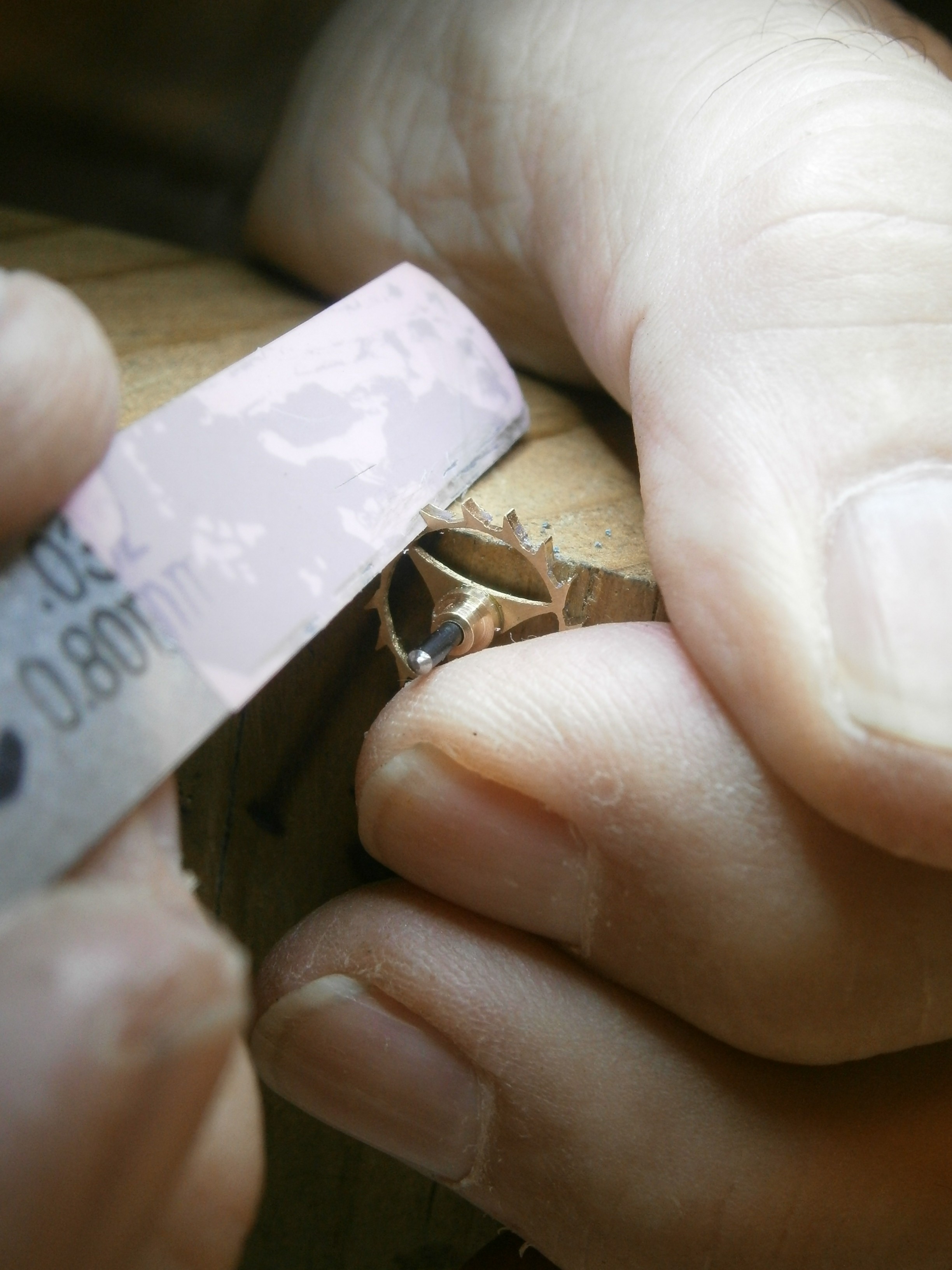
I finished by lapping the working face to a polished finish, first on a diamond lap and then with progressively finer grades of diamond coated film, ending with the pink 1 micron grit shown in Figure 11. Tungsten carbide has a hardness of about 9.5 on the Mohs scale and on an absolute scale is somewhat harder than ruby, so I do not expect it to wear out.

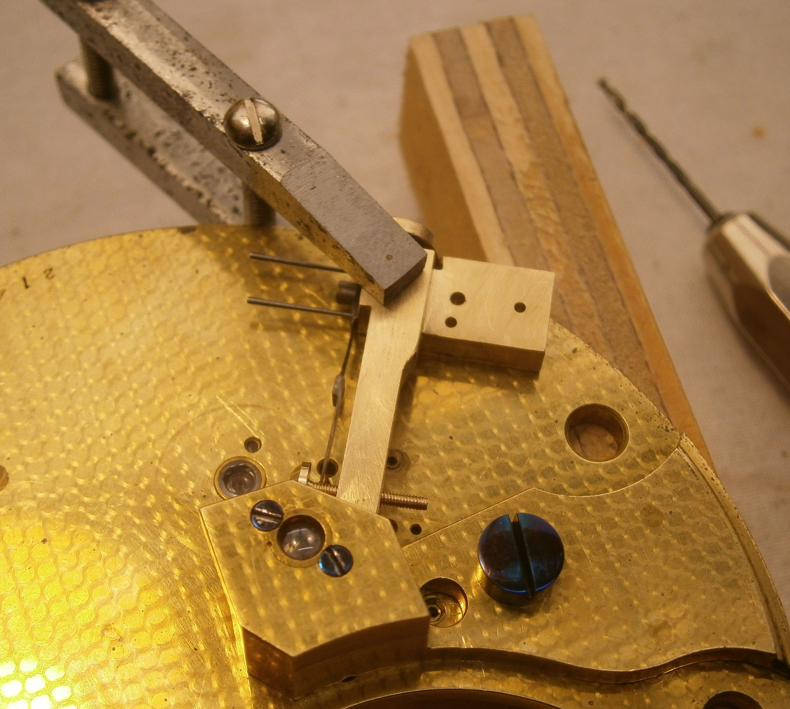
I have a stereo-microscope mounted on an arm above my work bench and certainly needed it to cement the new stone in its holder using flake shellac. It leans forward about 12 degrees, and getting it to sit at this angle while still sitting squarely in its holder took many anxious minutes of softening the shellac with a soldering iron, readjusting, checking the angle from the side, and checking for squareness from the front before I was satisfied. In intervals, as I worked out how to hold and shape such a tiny piece, easily mistaken for a piece of dust, I cleaned the plates and every other part, removed old grease from the mainspring and stop work, checked every link of the chain for stiffness, cleaned out pivot holes and jewels, inspected pivots for wear, resilvered the dial and applied oil and grease as necessary to moving parts.

Adjusting the escapement

The problem with this is that adjusting one part of the escapement results in a change to another part. It is as well to start by checking that the rollers and lower balance spring stud are in the same angular relationship as before starting the overhaul, in the hope that no previous unsuccessful attempt has wildly upset the relationship. I reiterate that the third wheel should always be blocked while each adjustment is made.

The chronometer is then put into beat so that the unlocking stone at rest lies just to one side of the passing spring, neither lifting it on the ‘free swing” direction nor tending to lift the locking stone off an escape wheel tooth in the other. This can be done preferably by turning the lower balance spring stud on the balance staff, since rotating the unlocking roller then upsets its angular relationship with the impulse roller.

At this point, the mainspring can be set up half a turn so that a tooth is locked and the locking stone depth into the tooth can be adjusted and both the draw and the locking checked. Too much depth slows down the unlocking so the impulse stone runs ahead of the tooth that is supposed to be providing the impulse, as well as perhaps missing locking on the next tooth. Too little depth also risks failure of locking or even tripping or running away (hence the mere half turn on the mainspring). Changing the depth by cautious adjustment of the banking screw of course changes the beat, which then has to be re-adjusted.

The depth of the detent into the unlocking stone also has to be adjusted. Too little combined with worn balance pivots or damaged hole jewel may lead to tripping or total failure of unlocking. Too much will give insufficient gap between the moment of unlocking and the arrival of the impulse stone, so that impulse is too feeble or missed altogether.

Supposing the happy state has been reached so that the balance can be set into motion, with a finger poised to stop the third wheel if necessary, if the motion of the balance accelerates, all well and good. Attention can then be paid to get a lively range of motion by making minute adjustments to one or other of the rollers. The impulse roller is usually set quite hard on its taper and is difficult to turn, so that a slip of the pliers may lead to the demise of the impulse stone. Normally, the unlocking roller is a friction fit on the balance staff and has a flat on it so that it can be rotated by a suitable home-made wrench.

After making an adjustment and restarting the movement, it may take several minutes for the balance to reach its maximum excursion of about one and a quarter turns, so enough time should be allowed for this to happen before judging whether an adjustment has led to a reduction in the motion that needs further adjustment in the opposite direction. It can be difficult to judge what the range of motion is and modern cameras and cell phones that make a slow motion video record are a great help. Eventually, a tiny adjustment of the unlocking roller converted a sluggish movement to a vigorous one. After adjustment of the timing nuts the three day rate at 20 degrees Celsius is 1.2 seconds losing. Figure 12 shows the final result after cleaning.

39: End result of overhaul

I am always happy to receive advice and constructive criticism from those who are better informed or with more experience than I have.

Advertisement


38: A Kelvin and James White chronometer overhauled.

19 04 2020

To find your way to other posts click on October, 2016 in the list of dates on the home page. This will take you to a List of Posts and other suggestions on how to navigate the site.

Captain Dave of Sydney liked what I had done for his old Usher and Cole chronometer (post number 36) and so asked if I would overhaul another antique chronometer that he had, which was in working order but which was in a dirty condition. I was happy to oblige him, with my usual condition that I would accept no reward nor offer any guarantee. Figure 1 shows the face of the instrument in the condition that I received it,

Face

Figure 1: Face of chronometer.

While some of the finer engraving had lost a little of its black wax, the silvering generally was in good condition and I elected not to interfere with it. Like a great many chronometers, sextants and fine clocks, the name does not necessarily indicate the maker as opposed to the retailer. Chronometer making during the nineteenth and early twentieth century was largely a cottage industry, with the “maker” putting together parts bought in from elsewhere, though the maker often was responsible for finishing and for adjusting the balance and escapement. According to Tony Mercer’s “Chronometer Makers of the World,” from 1906 onwards the movements for Kelvin and James White were made by Mercer, so number 7506 dates probably from late 1906.

Bottom plate stamp

Figure 2: Perhaps John and ?Thomas Travers’ mark on top plate.

The craftsmen who made the various parts often had no means of promoting themselves except by including a mark. We have seen in post 36 how George Cotton and Sons marked the mainsprings they were noted for supplying to Mercer and Kullberg among others. Until 1907, Mercer’s plates came from Prescott in Lancashire. Figure 2 shows the initials J&T.T on the top plate of 7506. John Travers (1849 to 1937), a distant cousin of Tony Mercer, had ten sons and the mark possibly includes one of them. Please correct me via a comment if this is wrong.

Bottom plate

Figure 3: Condition of bottom plate.

Figure 3 shows the condition of the bottom plate and the top plate was in a similar condition. While no actual dirt is shown, one can see where oil has migrated onto the plate.

Figure 4 shows the dial side of the lower plate, where it can be seen that the pillars have been rivetted in place. This is probably a little more labour intensive than simply drilling and tapping the pillar for a screw and does mean that the two ends of the pillars are not interchangeable. Note too the collection of four punch marks to identify the plate. Apparently, they were routinely made in four pairs, sometimes with a fifth pair identified by an extra punch mark above the others.

Pillar rivet

Figure 4: Rivetted pillars and punch marks, bottom plate.

Figure 5 shows one side of the so-called English detent, and Figure 6 shows a general view from the other side. Making a detent was acknowledged  to be one of the more difficult tasks and was a very specialised one. It was filed up from a solid block of steel and must have occupied many hours of work, with the expenditure of several files. A very high “black” polish was considered necessary, in which a highly polished surface looks shiny from a particular angle that changes suddenly to black when the angle changes.

Copy of Detent not passing

Figure 5: Horn side of “English” detent

I am unclear as to why such a high polish was thought necessary. Certainly, there should be no scratches on the spring that might act as stress raisers leading to failure, but a high polish of the rest seems to be due to tradition.  No adjustment was possible of the depth of the horn or passing spring into the discharge pallet and the position of the passing spring on the horn had no adjustment other than one involving removal of metal. My next post will show how Mercers eventually made both relatively easily possible.

A disaster seems to have occurred at some time, as the locking stone is of steel instead of ruby. A L Rawlings in his “The Science of Clocks and Watches” describes how a chronometer having a hard steel impulse “stone” and dated to 1840 was working a hundred years later without any signs of wear of the escape wheel or the impulse face of  the stone, and there seems to be no reason why the same should not apply to the locking stone. My own practice is to make a replacement locking stone out of tungsten carbide, which is both harder and stronger than ruby.

Detent GA

Figure 6: Passing spring side of detent.

Easily visible in Figure 5 and just visible in Figure 6 is the end stone of the escape wheel and it lies well below the surface of the plate. The reason for this became plain when I examined the upper pivot of the escape wheel (Figure 7).

E wheel pivot

Figure 7: Upper escape wheel pivot.

Probably as part of the same disaster that overtook the locking stone, the upper pivot had at some stage broken off and been replaced by a new pivot soft soldered in place in a pipe which was soldered into the escape wheel pipe. To many horologists this would be a terrible sin and there may well be better ways of tackling the problem, but the result in this instance functions well, if you like an engineer’s solution of which I feel bound to approve. However, the length of the arbor was shortened thereby and so the hole and end stones were lowered into the plate to compensate.

I find it nerve wracking to drill into an arbor, for if the drill jams and breaks off in the hole it is a minor disaster, which I prefer to avoid when it is possible to graft on a muff (See Post 7 of 23 July 2013). I now secure the muff with shellac rather than Loctite so that it is possible to make minor adjustments in length simply by softening the shellac with a soldering iron applied to the arbor. This is a good point at which to emphasise that one should always block the movement every time when making any adjustment to the balance that involves its removal, even when it seems to be unnecessary. I have had very good cause to regret not doing so when tired. The escape wheel ran away, shearing off the locking stone, bending the passing spring, buckling the detent and breaking the upper pivot.

In 1904, the Swiss, Charles-Edouard Guillaume, published his study on nickel steels “Les Applications des Aciers au Nickel,” the best known of which are Invar, which has a coefficient of thermal expansion of near zero and Elinvar, the elasticity of which remains practically constant with change in temperature. As his grandfather and father were watchmakers, it is perhaps not surprising that Guillaume soon saw an application of Invar to timekeeping. Prior to this, chronometers had a gaining temperature error between two temperatures at which there was no error, because the effective radius of a bimetallic balance reduced nearly linearly with increased temperature, but the elasticity of the spring reduced with the square of the temperature. Outside the two temperatures there was a losing error. There were many ingenious attempts to reduce this “middle temperature error” and 7506 has one of them due to Kullberg (Figures 8 and 9).

Aux comp 2

Figure 8: Auxiliary temperature compensation, from below.

Aux comp side

Figure 9: Auxiliary temperature compensation, side view.

The outer ends of the rims are split to form, as it were, what I will call compensating arms. These arms  carry auxiliary compensation weights, the outward movement of which is limited by an adjusting screw. With increasing temperature, the arms move in together, eventually leaving the end of the screws behind so that the moment of inertia is slightly decreased and the losing error compensated. With falling temperature the arms contact the ends of the screws and the rims and compensating arms act as one. With a suitable choice of temperatures at which there is no error, not only is the middle temperature gaining error reduced, but also the losing error in the higher temperature range.

Aux comp screw

Figure 10: Broken auxiliary compensation screw.

It is possible that someone misunderstood the purpose of the auxiliary compensation and thought that the tiny screws, about 0.8 mm in diameter, were for fine timing adjustment. Instead of leaving well alone, he twisted off the head of one of them, as shown in Figure 10. There was nothing left in which to cut a screw driver slot and so I attempted to grasp the inboard end of the screw with a fine surgical needle holder (Figure 11), grinding down the ends so as to enter the slot.  I was able to get a firm grip on the end of the screw, but on attempting to release it only succeeded in breaking it off.

Needle holder 001

Figure 11: Modified needle holder.

As the only remaining solution was to drill out the remains, this was not a disaster and I was eventually able to drill out the remains by hand using a tiny self centring drill held in a pin vice. The drill wandered a little so I had then to re-tap the hole to a slightly larger size and make a screw to fit, leaving its tip in the same position as the one on the other side.

O haul dates

Figure 12: Overhaul dates.

The back of the face carries what I assume are dates of overhaul by the same person as the form of the digits is the same. It appears to have been overhauled in December 1909, March 1917, February 1924 and February 1927. A different hand has added faintly what is possibly February 1930. After cleaning and oiling I was tempted to add 12/19 with my initials, but resisted the temptation, as posterity owes me nothing.

I was able to adjust the rate to less than two seconds leaving further adjustment to Captain Dave, but my ambition to see how the temperature compensation fared at different temperatures was frustrated by a prolonged summer and the inability of my oven to cool over a greater range than 8 degrees Celsius (See postscript to post number 37).


37: A makeshift oven to rate chronometers.

25 01 2020

On page 95 of “The Mariner’s Chronometer” I mentioned briefly that the amateur could rate a chronometer at various warm temperatures using a makeshift heating oven and use a domestic refrigerator for low temperatures. At the moment, my area of New Zealand is enduring a drought combined with something of a heat wave, with temperatures reaching 31 degrees (88° F) in the last few days. This coincided with my wish to rate a Mercer chronometer dated to 1907 at various temperatures, as its balance rim  is fitted with a device designed to compensate for middle temperature error. I will be writing about it at more length in my next post.

In the last few weeks, night time temperatures have never fallen below 18 degrees (64° F) and maximum day time temperatures indoors have often exceeded 25 degrees (77° F), so I determined to make an oven that could not only maintain high temperatures (which is relatively easy) but also maintain temperatures below the ambient temperature (which is not).

An old mechanical room thermostat  was not equal to the task as its response was very slow and it could not maintain temperature to closer than four or five degrees, so it found its way out of the scrap treasure chest into the waste bin. While waiting for a modern electronic replacement and  Peltier device to arrive, I gathered together other bits of treasure hoarded over the years and assembled them into the untidy lash-up shown below in Figure 1.

Oven 001

Figure 1: Power supplies and control unit.

The enclosure is simply a polystyrene box that once protected an antique sextant on its way across the world to me and I was very happy to re-purpose it and keep it from polluting the environment, at least for a time. A small motor salvaged from a photocopier drives a circulating fan inside the enclosure and is powered from a small 12 volt transformer and a rectifier bridge made up of four large silicone diodes that are rated very far in excess of what is needed. A rectifier converts alternating current to direct current, which some motors and most electronic devices feed on.

A large salvaged 12 volt transformer feeds through another bridge rectifier to the Peltier device. This is a bunch of n-p junctions that form a large thermocouple working in reverse. When voltage is fed in, one side of the junctions becomes hot and the other side cools down, provided the heat from the hot side is conducted away into a large heat sink which is force-cooled by a powerful mains-powered fan. If the fan should fail, the hot side becomes very hot indeed, with the cold side not very far behind, so it is protected from such a fate, by a thermal switch applied to the  heat sink.

The control unit or thermostat is an STC-1000 digital device bought from e-bay for a relatively small sum. It is powered by 240 volts a.c., has a wide temperature range, can handle 10 amps d.c and can maintain temperatures within a single degree. The instructions that came with it have a “Chinglish” flavour and are hard to follow, but the device itself does all that is claimed for it.

The Peltier device is sandwiched between two heat sinks, and, since the interior side gets cold, I have called it a cold sink (Figure 2). A small circulating fan keeps the air moving over the sink and around inside the enclosure. Both fans run all the time. If the temperature exceeds the set temperature by half a degree, the control unit switches on power to the Peltier device, which operates until the set temperature is reached, when it is switched off. If the temperature falls by half a degree, the Peltier device is switched off, the light bulb is switched on and  the temperature rises to the set temperature, when it is switched off . Thus the temperature inside the enclosure is held to the set temperature ±½ a degree and the average temperature is the set temperature.

Oven 002

Figure 2: Interior of enclosure.

The owner of the chronometer has kindly agreed that I may keep it to study its response to different temperatures, so I will do so for a week each at 30, 25, 20, 15, 10 and 5 degrees. I will report back when I cover the overhaul of the chronometer itself.

Post script, 18 April 2018: I was not able to do as I had hoped: to study the response of an antique chronometer at various temperatures, as I found that the Peltier device was unable to sustain a temperature gradient greater than about 8 degrees. At this time, the daytime temperature seldom dropped below 25 degrees and was frequently higher, so my ambition failed. However, as winter approaches, I should be able to maintain a wider range of temperatures, since it is much easier to raise the temperature than to lower it.


36: Usher and Cole’s Finest.

18 09 2019

By double-clicking on them, most of the photos can be enlarged. Use the back arrow to return to the text.

While I have been fairly busy since January restoring sextants and chronometers, I have not been very good at writing blog posts and have some catching up to do. In early June, I heard from a new friend in Sydney who had in 2009 acquired a chronometer made by the makers Usher and Cole some time before July, 1897. The chronometer had never run since Captain Dave first owned it. A clock maker in Sydney had managed only to break off the minute hand. Could I help? I was happy to agree on my usual terms of every care taken but no guarantee given and no reward accepted, so later in June the instrument arrived at my home in Pukenui, New Zealand.

We know something of its earlier life, as it had been on trial at the Royal Observatory in Greenwich between July 3rd 1897 and 22nd January 1898 prior to being accepted for purchase by the Admiralty. It was described as having “Auxiliary to balance acting in heat and cold. Palladium spring”. Over the six month trial the difference between the least and greatest rate (a) was 19.4 seconds and the greatest difference in rate between one week and the next (b) was 5.6 seconds, giving it a trial number (a + 2b) of 30.6. Its least losing rate per week was -1.6/week and its greatest gaining rate was +28.1/week, not great by modern standards, but considered adequate in the days before the arrival of the Invar group of alloys. Bear in mind that by 1897, all Naval ships were steam powered and unlikely to be for a prolonged period away from ports where chronometers could be checked.

The chronometer duly acquired its broad arrow and disappeared from view until after the Second World War, when it was in use by the Australian Civil Aviation Department to check air navigation aids. Figure 1 shows its face before restoration to health.

Face before

Figure 1: Face on arrival.

The silvering was in poor condition. Note for future reference that it has stopped at 48 hours.

Problems

I quickly had it apart and found that as well as the broken minute hand, the upper escape wheel pivot was broken, the detent was in several pieces, the oil was green and of the consistency of thick glue and the mainspring had broken into three pieces at the barrel end.

Dead pivot

Figure 2: Dead pivot.

Trials of re-pivoting

What should have been a relatively simple task of making a muff and applying it to the arbor (https://chronometerbook.com/?s=Repivoting+part+2) became a major problem when, during turning down of  the arbor, it snapped off flush with the top of the pinion. I dealt with this by drilling right through the pinion, taking extraordinary care to ensure that the hole was well-centred and straight, and then making a complete new arbor to which I then glued the pinion with Locktite.

Carbide drills sold for circuit board work are sharpened by the four facet method which means that in principle they are self-centring, but if the tail stock of the lathe is not truly concentric with the axis of the lathe spindle, being brittle they will wobble and then break as the hole deepens. I use a stereo-microscope permanently mounted on my medium-size lathe and if there was the slightest sign of wobble, I adjusted the set-over of the tail stock until there was none, before drilling through. I have increased the rigidity of the drill to some extent with epoxy putty. Figure 4 shows the result before polishing and assembly.

OLYMPUS DIGITAL CAMERA

Figure 3: Starting centre.


Esc wheel arbor exploded

Figure 4: New arbor with pinion and escape wheel.

Of course, those handy with a graver might have used one to make a true centre before using a spade drill held in a pin vice and guiding it by hand through the pinion.  I prefer to use the “iron hands” of the modern lathe to do the same thing, as I have not enough years left to spend them learning old techniques. Happily, both the pinion and the escape wheel ran truly after assembly.

New detent and support block

The detent posed a complex problem for an amateur like me, as the makers provided no means of adjusting its position on the top plate, but attached it directly to the plate. Figure 5 is a sketch from Marvin E Whitney’s “The Ship’s Chronometer” to show the general layout and dimensions of an English detent.

English detent

Figure 5: Means of mounting “English” detent.

Instead, and with Captain Dave’s permission, I elected to make a detent of more modern pattern and attach it to a support block so that its depth into the escapement could be adjusted by means of the screw seen on the left of Figure 6. See posts 22, 33 and 34 for details of making a detent.

Detent lab

Figure 6: Detent and support block.

Locking stone and passing spring

The locking stone had perished in the disaster that had destroyed the detent and the passing spring was absent, so I made the stone from tungsten carbide (see post 24) and the passing spring from 0.05 mm brass shim stock by the crude method involving fine scissors and finger nails described in the later part of post number 22.

Support block

I carved the support block out of a scrap of brass to the dimensions and shape of one from a Soviet MX6 chronometer (Figure 6). When it came to fitting it , I failed to notice that it overlaid the position of the third wheel arbor, and so had to file a cutout for the arbor. Once I had settled the position of the block, with the detent pointing to the centre position of the Balance wheel arbor (Figure 7), I clamped it to the top plate with a roughly made little clamp before spotting through for the steady pins and attaching screw (Figure 8).

Align detent horn

Figure 7: Aligning horn of detent.

Align support block

Figure 8: Mounting the support block.

Minute hand

Fortunately, both parts of the broken minute hand were present, so it was the work of only minutes to soft solder them together, leaving a generous fillet underneath where it cannot be seen.

Mainspring troubles

I next cleaned all the parts during which I discovered that the mainspring had broken into three parts (Figure 9). Until more modern steels were developed, this was a moderately common occurrence, so suppliers stocked a very large inventory of springs.

Broken mainspring

Figure 9: Mainspring, barrel and arbor.

I was interested to find the signature of the makers on the inside of the broken middle part and wondered whether this had perhaps been a stress raiser that contributed to the spring’s eventual failure (Figure 10). The whole of the inscription reads “Geo Cotton & Sons. Feb 1902”.

Usher and Cole 009

Figure 10: Spring maker’s mark.

I was able to obtain what was possibly the last spring of identical dimensions on the planet.  I checked the length of the original spring with a tape measure and double checked by using the usual formula that takes into account the thickness of the spring, the internal diameter of the barrel and the external diameter of the arbor. They agreed with each other and so I cut the new spring to length with a few extra centimetres for good luck.

When it came to winding the spring to fit it in the barrel I was perplexed to find that I could not get the arbor hook to engage, try as I might to shape the inner end of the spring, and eventually discovered that the hook had lost its edge. There was not enough of the old hook to file it to a new hook, so I filed away the old hook and drilled a hole at 90 degrees for a new one. Once fitted, the outer end kept slipping of its hook, so I was obliged to remove it and fit a new one there as well.

All the parts were now ready to be assembled (Figure 11), I fitted them all together, set up the mainspring a cautious single turn and the tired old chronometer sprang into life at once. However, when I tried to set it up the usual six plus turns, I found that only five and a quarter were available and had to adjust the chain to make the stop work act earlier (about which, more later), lest a future owner wind it so hard as to rip the barrel hook out of its moorings. It then ran for a maximum of 48 hours, rather than the more usual 56 plus. In practical terms, this is insignificant, since two day chronometers were always wound daily at the same time.

Top plate GA

Figure 11: View of top plate.

It seemed to be a pity to leave the dial as shown in Figure 1, so I stripped the old silver off,  graining the dial in the process, using fine emery paper and refilled the engravings with sealing wax stained black (See post number 9). I used a proprietary substance , probably silver chloride, to re-silver, and stabilised it with cream of tartar. Lacquering  clock faces is a skill that I have not learned, so I finished the face by polishing with silicone wax polish. I did the same with two clocks I made about fifteen years ago and the silver has not yet tarnished, though I live far away from any industry or busy roads, so this is perhaps not a good test of its efficacy. Figure 12 shows the finished face. Captain Dave learned a lot about polishing brass when an apprentice, so I left the bowl for him to do.

Face under bezel

Figure 12: Re-silvered dial.

Now for some points of interest that do not appear in more modern chronometers.

Stopwork

If there were not some means of bringing winding to a halt, a ham handed person might well continue winding until the chain or the barrel hook gave way, so all clocks fitted with a fusee have some means of stopping the winding. Figure 13 shows the top of the fusee. The comma-shaped object is called a snail.

OLYMPUS DIGITAL CAMERA

Figure 13: Fusee snail.

Turning now to Figure 14, which shows the underside of the top plate, we see the fusee iron, which is spring loaded to rest against the chain as it approaches the top of the fusee during winding. Eventually, the chain raises the iron to a position where the end of the iron butts against the projecting snail, bringing winding to a positive halt. Notice in passing that even the undersides of the plates have beautiful decoration, though only an overhauling chronometer maker would ever see it.

Stop work lab

Figure 14: Fusee iron.

Auxiliary temperature compensation.

As the temperature rises, the material of the balance spring becomes less elastic and the chronometer tends to run slower. Meanwhile, the material of the balance rim has become larger, also slowing the chronometer., so the rim is made of brass on the outside and steel on the inside. Brass expands more with heat than steel and the effect is for the ends of the balance rim to move inwards, decreasing the mean radius of the rims and tending to compensate for the slowing effects of temperature.  However, it was discovered that if the compensation is correct at two temperatures, the chronometer runs slower  midway between them, the so-called middle temperature error. In other words a graph of compensation versus temperature is convex downwards.

Much ingenuity was expended in correcting for the middle temperature error to, as it were, flatten the curve to make it more linear. Figure 15 shows two such auxiliary compensations in the same chronometer. Poole’s acts at a given temperature at which it interferes with further expansion of the rim at lower temperatures, while Mercer’s comes into action at higher temperatures, when the short bi-metallic strip moves the weight inwards and reduces the moment of inertia a little. A much fuller description can be found in Rupert T Gould’s magisterial book, The Marine Chronometer: its History and Development.

Copy of Aux comp 1

Figure 15: Auxiliary compensation.

Charles-Edouard Guillaume’s studies of nickel-iron alloys led to the invention of Invar, which has a very low coefficient of thermal expansion and of Elinvar, which has a practically constant elasticity at temperatures likely to be survived by human beings. Combining Invar in the balance rim and Elinvar in the spring nearly eliminated the middle temperature error. For his studies, Guillaume deservedly won a Nobel prize in 1920. The Hamilton Watch Company’s invention of the ovalising balance further reduced compensation errors to a practical minimum.

Rate

How well did this old chronometer perform? Figure 16 shows its very creditable  rate over 5 days, winding every 24 hours. There is a small deviation from the mean, a maximum of about one second at 70 hours, which would translate into a quarter of a nautical mile error in longitude at the equator. However, when allowed to run down to 48 hours, the losing rate changed to a gaining rate at about 30 hours, no doubt because the short mainspring began to deliver less power at this stage.

U and C rate 2

Figure 16: Rate over 5 days.

Maybe some of my methods would not gain the approval of all professional restorers, but I can say with Galileo Galilei “E pur si muove“, “And yet it moves”. And Captain Dave is happy too.


35: A Post-WW II Glashütte Chronometer

10 01 2019

In the 1930s marine chronometer production in Germany was centred on Hamburg and Glashütte-bei-Dresden. German watchmaking had originated in the small town of Glashütte and by 1934 was in difficulties. The armed forces had been a significant buyer of high-class chronometers prior to the First World War, but the loss of the German Navy following the war had led to a sharp decrease in demand. The town Council proposed a programme to make 500 instruments over five years and in July 1935 a meeting was held in Berlin involving the ministries of war, transport, education and aviation, with input from the mechanical and optical manufacturers and Deutsches Seewarte (the German Naval Observatory).

This led to the German armed forces being directed to survey their holdings of chronometers and to their  scrapping about 65 percent of mainly English chronometers. Arthur Lange and Son developed their Normal-Chronometer, a classical marine chronometer with spring detent, fusee and chain. This gave way in about 1940 to the design of the Deutsche-Einheits-chronometer or German Standard Chronometer which went into production by Gehard Wempe of Hamburg, who had taken over Hamburger Chronometerwerke GmbH from the ship builders of the city in 1938. Wempe began production of the Einheits-chronometer in 1942 in association with A Lange and Son. Production of parts was divided between the two firms. In all, about 2750 were made, presumably with serial numbers not starting at 1, as I am the guardian of number 3018.

At the end of the Second World War, Glashütte was under Soviet control and was obliged to make 250 chronometers for the Soviets as reparations, as well as providing a full set of drawings for the Einheits chronometer, which allowed production of the identical Soviet MX6 in Moscow. Then chronometer making was resurrected in 1951 in a nationalised firm termed VEB Glashütter Uhrenbetriebe (People’s Clock-making Company), formed mainly from A. Lange and Son and Mühle and Son. This company resumed making chronometers to a pre-war design which differed in a few respects from the Einheits-chronometer and the Soviet MX6. Production ceased probably in 1978, before re-unification of Germany.  Early dials gave the full information shown in Figure 1, while later ones had simply Glashütte in the centre (Figure 2) though the GUB stamp continued to be marked on the upper plate.

dial 2 001

Figure 1 Early face.

13 face

Figure 2: Later dial.

I was able to buy an example in a very poor and dirty condition, not going and for a relatively modest price. Figure 3 shows the condition of the plates as found…

1 ga dirty

Figure 3: Condition of the plates as found.

…while Figure 4 shows the state of one of the balance pivots. Everywhere, the oil had dried to the consistency of a hard soap.

3 dirty pivot

Figure 4: Dirty balance pivot.

Careful cleaning of the plates resurrected them enough to make the maker’s mark readable on the top plate (Figure 5). In restoring the much corroded and scratched plates, I tried to compromise between removing scratches and preserving the once-beautiful decoration. Practically all makers decorated the plates in some way, even in times of war, and even though they would normally only be seen at overhaul by the chronometer maker. This was true of the Einheits-chronometer, even when economies were being made by making the bowls of black Bakelite.

10 trade mark

Figure 5: Maker’s mark (GUB Glashütte/SA).

Figure 6 shows the completed cleaning. I was not able to remove some stubborn finger prints without risking the decoration.

7 ga stopped

Figure 6: Cleaning completed.

The Einheitschronometer and MX6 had only three pillars with their positions shown by  white circles in Figure 7, whereas the GUB version and its pre-war predecessor had four. The position of the extra pillar is shown by a black circle and Figure 8 shows on the left how the attaching screw also secures the barrel plate. In the other chronometers, the the top plate is threaded for screws that attach the barrel plate to it.

top plate mx6 001

Figure 7: Position of pillar holes (MX6).

2 pillars

Figure 8: Pillars of GUB chronometer

During WW II, some German chronometers were fitted with a steel band made by Sandvik of Sweden instead of the traditional chain. I have alluded to possible reasons for this in Post number 27, in which I describe substituting flexible steel cable for a chain. It is possible that in post-war East Germany, the craft skills for chain making simply did not exist. The band, 730 mm between the bights of the hooks, is shown in Figure 9, and is approximately 0.2 mm² in cross section.

9 band

Figure 9: Driving band and hooks.

Figure 10 shows the band in place on the barrel. Fitting it can be difficult as, unlike a chain, it cannot simply be wound on to the fusee and left there prior to attaching it to the barrel, on account of its springiness. It has to be wound on to the fusee with the latter in place between the plates and, while maintaining tension on it, the barrel is put into place, the hook attached and the barrel rotated to take up the tension and its click engaged. Before working out how to fit the band, I despaired a little and instead fitted a chain, only to find that the height of the chain meant that it fouled a head of the screw that attaches the stop work to the top plate before the final turn. As a result, the chronometer could be wound only to 48 hours instead of the usual 56 hours.

8 band in situ

Figure 10: Driving band in place.

The stop work for all but very early Einheits-chronometers and the MX6 is incorporated into the top of the fusee in the form of a transverse rectangular bar which can slide out of the fusee against a spring load. As the chain reaches the top of the fusee, it presses on one end of the bar to make the other end of the bar project, and this end then encounters a stout pin projecting from the underside of the top plate, bringing winding to a halt.

The GUB chronometer, however, uses Geneva or “star wheel” stop work, which is shown exposed in Figure 11. As the fusee rotates, a pin projecting from its top engages with the star wheel and makes it rotates through part of a revolution until eventually it buts against the part where there is no gap between the “teeth” and prevents further rotation. A leaf spring prevents unwanted rotation due, say, to vibration. I have illustrated a slightly different form of this mechanism in Figure 7 of Post number 20.

4 geneva 1

Figure 11: Geneva stop work.

Figure 12 shows the stop work in place and the screw head that prevented the final turn of the fusee. When fitting the driving band, and before fitting the top plate, the star wheel should be rotated so that the fusee can engage with a gap in the wheel and so that fusee can make all its turns. The top plate is then assembled, the fourth wheel blocked and the fusee hook engaged with the fusee, which is then wound while feeding in the band under tension, as described above.

5 geneva in situ

Figure 12:  Stop work in place.

I found the detent a little difficult to fit, as the foot of the support block lies partly behind a pillar (Figure 13), unlike the other chronometers where the foot is clear of the the pillar, as shown boxed in red in Figure 7. I found it easiest to invert the movement so the top plate is horizontal and then to tease one steady pin of the support block into place, having first roughly aligned the axis of the detent with the balance staff and rollers. Another difference in the detent is that it cannot slide axially on the support block, as its steady pins engage in holes rather than in a slot, meaning that the depth of engagement with the discharge roller is fixed.

detent

Figure 13: Detent.

The chronometer reached me with only the bowl and gimbals. The finish of the ring and brackets is very good compared to that of the MX6, which is, to borrow the words of an Australian friend, a little agricultural, referring to the finish of agricultural machinery.

OLYMPUS DIGITAL CAMERA

Figure 14: Bowl and gimbals

As there was no case, I had to make my own from a very battered old desk, using a mixture of MX6 and home-made brass furniture. The corners have mitre joints which are relatively weak, but when provided with keys and using modern glue, they are almost indestructible (Figure 15).

mitre

Figure 15: Cross section of keyed mitre joint.

The final result is shown in Figure 16. These chronometers were not brass bound, nor were they supplied with a top lid, which often were in any event removed and lost. The pivots of the balance staff on close inspection, were slightly worn and the upper pivot of the escape wheel was broken. I elected to accept the former and repair the latter using a muff, but found the rate irregular, sometimes to the tune of two seconds a day, so eventually I bit the bullet and made a new balance staff. So far, the variation in rate seems to have improved.

case

Figure 16: Chronometer in its case.

I found Das Deutsche Einheits-Chronometer (Altmeppen, J. and Dittrich, H., Kinnigswinter, 2012) very informative on the history of Glashütte and highly recommend it as a source of information, even for those who, like me, struggle to read German.


34: Yet more on making a detent

27 12 2018

(You can enlarge most of the figures by clicking on them)

In post number 22 of June 2016 I described my attempt to machine a spring detent, rather than laboriously filing it to shape and size. By post number 33 of September 2018, I had advanced to the stage of being able relatively rapidly to progress to the stage of having machined the detent all over, except for the spring. I had attempted, unsuccessfully, to surface grind the spring, and still relied on hand filing to reduce the machined spring to size.

At this point, Alan Heldman of Birmingham, Alabama kindly put me in mind of another method of finishing the spring to size, a method described on pp134 -137 by Robert J Matthys in his book “Accurate Clock Pendulums.” (Oxford University Press 2004). The method is described for making solid one piece springs for pendulum suspensions, and as these are typically 0.006 ins or about 0.15 mm thick, close to a typical 0.08 mm for detent springs, I though I would give his method a try. I have owned a copy of his book since 2006, but had never paid much attention to suspension springs.

Essentially, the method uses the side teeth of a small diameter end mill to reduce the spring to the desired thickness, supporting the reverse side using plaster of Paris. Using a Bridgeport vertical milling machine, a well-known full-size vertical milling machine, he found that he could not make springs thinner than 0.004 ins (0.10 mm) without tearing, using a brand new cutter, but I was hopeful that using my near-new Optimum Maschinen BF20V milling head and a brand new cutter, I might do a little better.

Having machined a detent as described in my last post, I set about making a simple jig to hold it while reducing the spring from a thickness of 0.3 mm to 0.08 mm. Figure 1 is a  drawing of the jig. I made it from a piece of ground flat 3 mm gauge plate. One hole is tapped M1 for a screw to hold the foot of the detent and the other is a clearance hole for a little M1 brass screw to occupy the tapped hole for the foot of the passing spring. Note the 1.5 mm deep counterbores on the back of the jig (Figure 2). Tapping deep holes with small taps is fraught with the danger of breakage, while long screws lose their heads easier than short ones; and the counterbores mean that both dangers are reduced. I made the screws out of brass so that recovery from any disaster would be easier, but as it happened, all went well.

The jig is of a length to be held easily in a machine vice, whose fixed jaw must be carefully aligned with the X axis of the machine table, preferably by using a dial test indicator. It could of course simply be clamped to the face of an accurate angle plate.

Detent jig drwg

Figure 1: Drawing of jig.


Jig

Figure 2: Rear of jig


Figure 3 shows the detent in place on the jig. The gap between the face of the jig and the spring can be seen clearly and the latter is without means of support against cutting forces. Matthys recommended filling this with plaster of Paris, known as POP to generations of orthopaedic surgeons until it was replaced by resin casts. POP sets quite rapidly, in a matter of minutes, especially if warm water is used, but then has little strength, but by 24 hours it has cured sufficiently for our purposes. It has the further advantage of setting to a solid from a quite runny mixture, so there is no difficulty in enticing it into narrow spaces.

On jig no pop

Figure 3: Detent attached to jig.


Figure 4 shows the process complete. I have cleared plaster from the face of the spring and encased as much as possible of the rest of the detent to prevent damage from accidental tweaking of the horn

Jig and pop

Figure 4: Plaster of Paris applied.


Figure 5 shows milling in progress. The cutter is a new 1.5 mm diameter, 3 flute titanium-coated end mill running at 2000 rpm. Matthys suggests a much lower speed of 325 rpm to reduce chatter, but it may be that there was wear or vibration in his milling head, as I noticed no problems with chatter marks. Aiming for a thickness of 0.08 mm from a starting point of 0.3 mm means that about 0.11 mm has to be removed from each face, so before starting to cut, I measured over the jig and the spring to give a datum. I then very gradually brought the cutter into contact, moving the workpiece back and forth as I did so. Once contact was made I very gently increased the length of the cut at each end until  radii were formed, and at these positions I locked the table stops so I would not thoughtlessly advance the cut beyond and perhaps break the cutter, a particular risk when advancing to the left. A cutter of this size can take only small cuts in steel and I put on cuts of only 0.02 mm at a time, running the cutter back and forth, blowing away the fine swarf until no more formed and then measuring. The latter needs great care to avoid rocking, as the anvil of a micrometer can reach only the edges of the spring, and it must also avoid the radii at each end .

Jig and cutter

Figure 5: Milling cutter in action.


Figure 6 shows the finished appearance of the milled surface. When the detent is removed from the jig, most of the POP falls away and the remainder can be carefully chipped off, followed if necessary by brushing off the remainder under water. I found that the plaster caused mild surface rusting, so subsequently, before each encasing in plaster I dipped the detent in a dilute solution of shellac in spirit, drying it with a few seconds burst from a hair dryer. The almost immeasurably thin coat of shellac cured the rusting problem, did not affect machining and was easily removed by a few seconds of boiling it in alcohol.

It was easy to machine the second surface by simply flipping over the detent on the jig and symmetry at the ends was assured by the table stops.

Jig and pop cut done

Figure 6: Appearance of milled surface.


For preliminary finishing I attached the detent to a scrap of wood with plaster, which not only gave support to the spring, but gave better control than I can get using my finger nails to hold it (Figure 7). After removing machining marks from everywhere except the spring using a fine file, I hardened and tempered the detent as described in post number 22. The slight scaling that resulted I removed by a few minutes soak in dilute sulphuric acid (battery acid) followed by brushing.

To polish, I used progressively finer grit emery paper glued to a strip of wood, finishing with 1200 grit. This seems to give a bright finish and saves messing about with traditional pastes of diamantine. Twelve hundred grit is about 15 microns in diameter. It is now possible to obtain plastic film with fine diamond grit embedded, down to one micron size and a kind friend sent me some of various grits to try, though I find it difficult to attach it securely to a substrate. I will keep on trying.

OLYMPUS DIGITAL CAMERA

Figure 7: Detent embedded in POP to polish.


Figure 8 shows the final result. With magnification and after polishing there are fine longitudinal striations visible in the spring which represent minute imperfections in the milling cutter teeth, but as they are so fine I elected not to attempt their complete removal as they are not likely to be stress raisers. The radii at each end on the other hand reduce the danger of fracture. As far as I can tell, there is a slight increase in thickness from top to bottom of around 0.015 mm, due either to flexure of the milling cutter, or backward  lean of the milling head. Since I checked for the latter only a few weeks ago, it is likely to due to the cutter.

Finished

Figure 8: Finished detent.

As always, I am happy to hear from readers who have constructive criticism or suggestions to make.


33: More on making a detent

26 09 2018

A little over two years ago I wrote on how I set about making a spring detent for a Soviet era MX6 chronometer by using mainly machining methods (Post 22 of 20th June 2016). I had to make the spring by filing and, after re-reading an account of how V.E. Van Heusen had mass-produced detents for the Hamilton M21 chronometer during WW II* it occurred to me that it is very unlikely that he produced the springs by filing. Indeed, it seemed to me that the only practicable way of making the springs in qualtity was by surface grinding. This involves passing a rigidly held workpiece beneath a grinding wheel and decreasing the distance between them by finely controlled increments until the desired thickness is reached.

The design of the M21 detent is such as to make this relatively easy, as it is feasible for one side of the spring to be supported while the other side is reduced to the correct thickness (Figure 1). This is not true of most spring detents, including that of the German Einheits-Chronometer (Figure 2) and the Soviet MX6 which is a very close copy of it.

Tims detent

Figure 1: Part-finished M21 detent (Courtesy of Tim White).


Copy of Einheitschronometer drwg

Figure 2: Drawing of Einheits-Chronometer detent.

Figure 3 shows a sectional drawing of the MX6 detent rather more clearly.  If one side of the spring is ground  and the detent is simply turned over to grind the other side and reduce it to thickness, the spring is unsupported in the middle part so is likely to flex against the cutting forces.

Detent section

Figure 3: MX6 detent section. Spring (green) not to scale.

A few weeks ago, I set out to see if I could produce a detent with a spring ground to size and emulate manufacturers who presumably did not have an old gentleman sitting at a bench patiently filing away day after day, at least not in the 20th century. The problem resolved itself into producing a simple jig to hold the machined detent securely while each side of the spring was ground. Figure 4 is an un-dimensioned drawing. For those not used to seeing engineering drawings, the top drawing is a plan view and the bottom a side view. The surface destined to support the spring I have shaded in green and the slot to accommodate the pipe of the detent is in red.

Detent Spring Jig 2

Figure 4: Jig drawing.

It is a simple matter to make the jig, starting by milling the bottom flat, drilling the two fixing holes and securing it to a hunk of cast iron that has been ground flat and parallel on both surfaces. Then the top is machined all over. When milling the detent I had left the bottom surface of the spring a measured 0.35 mm below the level of the foot and taken 0.2 mm off the top surface, leaving an allowance for grinding of just under 0.2 mm, about the maximum that could be milled without distorting  the spring, which was supported only at the ends and one side. Thus, after milling the top of the jig, I had to lower the cutter 0.35 mm to do the rest, followed by a further 1.5 mm to cut the slot for the pipe. Figure 5 shows the jig against the partly milled detent, still attached to its parent metal.

Jig against protodetent

Figure 5: Jig against detent-to-be.

Once freed from its parent metal it was a simple matter to attach the detent to the jig with flake shellac, by heating the jig on an upended domestic iron, melting on some shellac and holding down the detent while the shellac cooled (off the iron, of course). I had hoped it would be a simple matter then to screw the jig to the cast iron block, trim a grinding wheel to a thickness of 5 mm and gradually reduce the spring to a thickness of 0.08 mm (Figure 6). It was not to be, as my horrible old Indian surface grinder refuses to do anything other than stick and slip when putting on cut, so my first attempt led to complete disappearance of the spring as  a cut, put on by measuring with a dial gauge, suddenly increased as I passed the detent under the grinding wheel.

Jig grinder

Figure 6: Jig on surface grinder chuck.

After remarking to myself how very unfortunate that was, I set about making an adapter to attach a small grinding head from my home-made Quorn tool and cutter grinder to the spindle of my light vertical milling machine, which has fine control over down movement of the quill. Making the adapter was a relatively simple turning exercise, but locking the spindle against rotation was not. However, I eventually succeeded, but in a moment of carelessness put on too much cut and ended with a spring a mere 0.02 mm thick. As making a detent involves annealing the metal to remove locked-in strains, and cutting and truing up a blank, before the detent can even begin to take shape, it takes me about three hours to mill one to shape, so I decided to leave grinding for another day.

However, it did occur to me that the jig would allow me to hold the detent more securely when filing  the spring, using my swing tool, so I made one more detent, which gave me an opportunity also to practice polishing. Figure 7 shows it in the swing tool. If you compare it to Figure 9 in post number 22, it will be apparent what I mean.

Jig swing tool

Figure 7: Jig in swing tool.

I am fairly sure that the procedure I have worked out to grind the spring is a workable one, and getting control of the grinding head downward movement is the nub of the problem, so I have not entirely given up the idea. It also occurs to me that attaching the jig to a piece of  flat plate  and screwing two hardened filing guides a few cm either side might allow reliable spring production by those without swing tools. Meanwhile, I have a spare detent, though it is not for sale… (Figure 8).

Jig detent finished

Figure 9: Finished detent.

There may well be machinists reading this who have much greater skill than I have and who may have faced and solved similar problems in the past. I hope they will not hesitate to contact me to put me wise.

*NAWCC Watch & Clock Bulletin, January/February 2012: The Man Who Saved the Hamilton Model 21 Ship’s Chronometer.


32: A chipped impulse jewel and another tale of woe

22 02 2018

In post number 30, I described how I made a new escape wheel for a Hamilton Model 21 chronometer and alluded to several other problems to be solved. In this post I will give a brief account of them, followed by a description of how I managed to avoid sourcing and buying a new impulse jewel. As the latter is tiny and rather difficult to photograph without sophisticated equipment, I apologise in advance for the sometimes poor quality of the photos, though I think they convey the details they are intended to convey.

As the fusee is one of the parts first to be removed, it revealed why I believe that the instrument had been dropped while out of its bowl (Figure 1).

Copy of Fusee damage

Figure 1: Damaged chain track of fusee.

Near the top of the fusee, the walls of the chain track had been bent out of straight so that the chain was wedged in place. I gently eased the chain out of the track and then, using a small screw driver with all sharp edges stoned off, I persuaded the walls upright again and filed off tiny burrs with a fine Swiss file. The damage is no longer apparent.

All of the pivots of the escape and balance wheels had been sheared off and the state of their hole jewels attested to the violence of the fall that had broken them (Figure 2).

Holestone damage

Figure 2: Destroyed hole stone of balance.

The plate jewels in the M21 chronometer are friction fitted into the plates and the throat of a staking set of normal size with the usual fitment for pressing jewels into place is generally too small to allow it to be used for a chronometer, so improvisation is needed to achieve a controlled pressure. I fitted the end stones first and then by careful and repeated measurement tapped the hole jewels into place with a brass drift until they were a scant 0.02 mm from touching the end stones. The official manual writes that they should be pressed into contact with the end stone, but it seemed to me that this might prevent the formation of an oil reservoir (if I am wrong, professionals please feel free to make a kindly worded comment). In retrospect I should probably have used a drift held in the tail stock of my small lathe as an improvised press with the plate resting on the  face plate.

I have described pivot repairs in posts numbers 6 and 7.

In early M21 chronometers, the plates and the detent were made of nickel silver, a brass in which half of the zinc has been replaced by nickel to improve its mechanical and corrosion resistance properties. There is no silver in nickel silver, but it is a shiny white metal. Columbia Metals UK describes it thus: “Nickel silvers are capable of providing a unique combination of strength, high modulus spring properties, corrosion and oxidation resistance, …. and numerous other attributes combined with ease of forming, machining, plating and joining.” Later chronometers have detents of beryllium copper. Happily, in the disaster, which seems to have included running away of the movement, my detent was “bowed but not broken” and the passing spring had survived . The two photos merged into one of Figure 3 were taken on different days in obviously different lighting, but are of the same detent from different viewpoints.

Detent merged

Figure 3: Bent detent.

The top image shows the detent in its support block and the bend at the base of the spring is rather obvious. Less obvious in the lower image is that the bend is not symmetrical and has introduced a slight twist. Only a fragment of the locking jewel had survived. By this stage, I had removed the passing spring. A few words of warning may be useful here. The screw that secures the spring in place is the tiniest part in the whole chronometer and can easily be treated as  a fragment of dirt and be lost, so it pays to store it safely in its own little container.

I straightened the spring by drawing it between the rounded jaws of special pliers, as described in post number 28 and eventually restored it to straightness. In an effort to avoid expense which I can ill afford, I attempted to make a new locking stone of tungsten carbide, as described in post number 24, for a Soviet MX6 chronometer, but the M21 locking stone is rather more slender at only 0.6 mm in diameter (versus 0.8 mm) and vibration from the belt of my tool and cutter grinder (since remedied) was enough to break it off when I attempted to grind the flats. I was thus obliged to buy a new locking stone and fit it as described in post number 15.

In early M21s the rollers were in one piece so that the mutual angles of the unlocking and impulse jewels was fixed, as in my example. Quite early on, the one-piece rollers were replaced by two separate parts. Figure 4 shows a view from a larger photo of the rollers from above, taken so I could replace them in their original position.

Copy of Rollers

Figure 4: Roller and jewels.

At first sight, all appears well, but as repairs progressed I discovered that the impulse jewel was quite badly chipped, so much so that a “replace and hope for the best” attitude would have been a poor plan. Figure 5 shows the jewel after removal.

17 Damaged impulse (2)

Figure 5: Chipped impulse jewel.

As I had not at that stage found a source of a new jewel, and doubted my ability to make a new one from tungsten carbide, I decided to reface it using a diamond file and laps, but first I had to devise a method of holding this tiny piece of synthetic ruby.  I filed a notch into a scrap of 2 mm brass sheet using a warding file until the jewel fitted snugly, and then secured it in place by melting a flake of shellac over it (Figure 6).

18 Impulse j set

Figure 6: Impulse jewel set into holder.

Note that this view shows that the damage extends quite a way down one edge of the jewel, so that in filing the new clearance the length of the jewel was quite considerably reduced. Looking through that most valuable of instruments, the retrospectoscope, I should have seated the chipped side in the holder and filed the new clearance on the other end. This would have maintained most of the length and made for a more secure re-fitting in the roller. A diamond file cut away the damaged face, much more easily than the same file cuts into tungsten carbide, and this underlines how much harder the latter is than ruby. As the clearance face comes into contact only with air, there was no need to achieve a very fine finish, but rather than leave a sharp edge, I rounded it a little with fine laps.

The roller is 6.35 mm (0.25 inch) in diameter, so another scrap of sheet brass with half of a 6.3 mm hole filed away provided the gauge to ensure that the tip of the jewel projected the correct length when being secured in place with melted flake shellac. This is described in post number 17.

Figure 7 shows the final position. Although the hold of the roller on the impulse jewel looks precarious, the shellac covers the base of the stone and I have left fillets of shellac on either face. If it does eventually give way, I will replace it with a carbide version.

20 Impulse j reset

Figure 7: Impulse jewel refitted.

The rest of the overhaul was routine and the chronometer showed no reluctance to resume its ticking with a very good action. However, I will end with a cautionary tale.

After about a week of rating it and finding that it had a very steady losing rate of about 1.7 seconds per day, its rate became erratic and then it lost two seconds overnight, so I stopped it and began to look for a source of the problem. As I was checking the balance and escape wheels for excessive end or side shake, the instrument suddenly declined to run at all. Suspecting that the impulse jewel had perhaps shifted, I removed the balance to check and found that it was still secure so I replaced the balance and turned my attention to the detent, to check what I already knew to be the case, that the escape wheel teeth were engaging about one third of the acting face of the locking jewel. The engagement was now much deeper. It was at this point that I discovered that, having at original assembly made a slight tweak to the depthing of the passing spring, I had failed to re-tighten the screw that holds the detent to the mounting block, labelled “detent clamp screw” in the original manual. Once I had tightened it, normal running resumed. Now I’m investigating its rate when half wound.


31: An eight day chronometer

14 02 2018

Some weeks ago, I received an e-mail asking about an eight day chronometer that the writer had recently inherited. He was able to tell me that it carried the name of John Carter of Cornhill, London and had been sold to the Admiralty in 1872. Its history between then and 1936 was not known, but in that year, it was sold by the Admiralty and in 1946 it had travelled to India with Ron’s uncle where it had remained on a bookshelf in a hot and humid climate until late in 2017.

After an exchange of e-mails, Ron sent me some photographs, which he has agreed I could share with others in my blog. Most of the photos can be enlarged by clicking on them. From Figure 1,  we can see that Carter did not actually make the movement. It was very common for retailers and even other makers to buy in finished movements and put their own names on the face. Makers would also buy from other makers if they had an order that they could not meet at the time. Parkinson and Frodsham as a company were active between 1801 and 1890. I cannot see a number anywhere on the movement that might give a clue to date of manufacture.

7 John Carter 738

Figure 1: Top plate inscription.

The form, size and layout of movements changed remarkably little from about 1800 until manufacture ceased in the 1980s and the same can be said for the bowls and cases. Two day chronometers of whatever make usually had three-tier cases forming a cube with sides of  185 mm, and heavy brass bowls of about 105 mm diameter. Almost always, the cases were brass bound with brass corners, presumably to hold them together in the marine environment if the glue and pins that held them gave way. Curiously, sextant cases, which would be a good deal more exposed to the elements than chronometer’s were almost never brass bound and the only one I have ever seen that was, other than so-called “reproductions”, is in my possession. Straight away, we see from Figures 2 and three, that my correspondent’s chronometer is an exception in the other direction.

1 john carter 738

Figure 2: Front of case.

2 John Carter 738

Figure 3: Side of case.

The front of the case has an interesting little escutcheon around the key hole, a bone or ivory lozenge, perhaps for the Admiralty to add their accession number to, and a broken button catch for the top lid. It is quite hard to find replacements for these little catches. The side view shows that the corners have rebate joints, another good reason for having the case brass bound, as they are less secure than dovetail or comb joints. We also see the two screws that secure the gimbals lock, the screw and rectangular washer that holds one side of the gimbals bearing and a standard drawer pull type of handle.

3 John Carter 738

Figure 4: Bowl in case.

On opening the case, we see a tipsy key  and gimbals lock whose forms did not change over time and between different makers of various nationalities. Unusual, however, is the way the tip of the gimbals lock engages with a brass band that nearly encircles the bowl, whereas usually it engages with a slot in a simple bracket that is attached directly to the bowl. The 15 mm thick walls of the case have dust seals of a darker wood, possibly ebony, let into the top of the bottom tier, except where the box lock and the hinges intervene.

4 John Carter 738

Figure 5: Face.

In an otherwise unremarkable 19th and early 20th century face is a clue that reveals the main interest of this chronometer (which is not to say that this venerable instrument is not desirable for other reasons). The state of wind indicator shows that the chronometer has a movement that runs for eight days. It is in a fully-wound state, while the minute hand is out of step with the seconds hand, whereas it should indicate a full minute when the seconds hand shows 60 (or zero, which amounts to the same thing).

Eight day chronometers are very uncommon and it is a little difficult to understand why any were made, since they would in practice be wound daily at the same time of the day to maintain a constant rate. The famous  and influential Captain Lecky, in his “Wrinkles in Practical Navigation“(ninth edition, London, 1884), writes “…it has been found that eight-day chronometers do not preserve altogether the same rate throughout the week; that is to say, that (though other conditions may be the same) their daily rate towards the end of the week will not agree with their daily rate at the commencement of it; notwithstanding which, the mean  rates of two consecutive weeks  may agree exactly.” He also adds “On account also of the lightness of the balance, the eight day chronometers do not go so well on board steamers which suffer much vibration from their machinery.”

Rupert Gould in his authoritative “The Marine Chronometer” confirms this when he writes (p.218) “...there is absolutely no advantage gained by making a chronometer go for more than two days between windings, and such machines are inferior both in principle and detail to the ordinary two-day pattern, although, if well-made, they may be found quite satisfactory in use at sea.

I reassured my new internet friend that it would not hurt to unscrew the bezel and tip out the movement. Figure 6 shows more details of the exterior of the bowl and the strange provision made for the tongue of the gimbals lock and the dust cover for the key hole. Note that the disc that houses it, attached with three screws, has the letters “H.S.”, followed by a broad arrow indicating government property, and the letter “I (or number 1). Perhaps we may tentatively wonder whether these letters refer to the hydrographic service of one of Britain’s former colonies.

6 John Carter 738

Figure 6: Exterior of bowl and GA of movement.

Turning to the general view of the movement, the most obvious difference from a two day chronometer is its exceptional height, necessary to accommodate a taller spring barrel and fusee, and that the rest of the movement, except for the centre wheel arbor, is sited between a sub-plate and the bottom plate. Figure 7 shows some more details of the spring barrel and fusee.

9 John Carter 738

Figure 7: The power source.

The the tall, large-diameter spring barrel accommodates about eight turns of  chain, while the fusee has about 16 turns, nearly twice as many as a two day chronometer, while the great or fusee wheel seems to have many more than the standard 90 teeth.

Another view of the power source (Figure 8) shows at lower left the elongated click of the maintaining power ratchet wheel attached to one of the pillars and, at top right beneath the top plate, the short pillar for  the fusee iron. This latter proved rather hard to photograph, so a verbal description will have to do. The fusee iron is shaped somewhat like a fork with two prongs. Its base is hinged to the short pillar and held off the top plate by a leaf spring. As the chain mounts the fusee during winding, it comes into contact with the underside of the fusee iron and raises it parallel to the top plate At about this point, a projection, called the snail, which is screwed on to the top of the fusee, enters the fork and brings winding to a halt. In the absence of  stop work, there is nothing to stop the heavy-handed from breaking the chain, with often disastrous consequences for the movement when the large amount of energy in the oversized spring is suddenly released. Also in Figure 8, the very large wheel for the state of wind indicator is seen at bottom right.

11 John Carter 738

Figure 8: Maintaining power.

This leaves the escapement, shown below in Figure 9. I have been able to show only the balance wheel and its associated parts The bi-metallic rim of the wheel is of course split adjacent to each timing weight which are situated as usual at the ends of the spokes, while large, wedge-shaped weights for temperature compensation are at roughly right angles to the spokes. The upper end stone seems to be of diamond mounted in a two-part balance cock. It is just possible to see the ruby locking jewel to the right of the spoke at seven o’clock and the ruby end stone of the escape wheel arbor to the left of the spoke. While in most modern chronometers the upper balance spring collet was attached to the top of the cock, in this instrument it has its own little pillar, and I wonder whether this might have been some form of compensation for middle temperature error, if the horizontal strip turns out on further examination to be bi-metallic.

Copy of 10 John Carter 738

Figure 9: Balance wheel.

I hope that this account may be of interest to those who, like me, have never seen an eight day chronometer “in the metal” as it were. Many more details of the structure of chronometers may be found in my book “The Mariner’s Chronometer”, available via amazon.com.

Post script 1 July 2018

Dave Murphy has kindly sent the following information about the markings on the chronometer bowl:

“You are correct on your reference to the H.S.3  markings on UK military chronometers.I can’t remember the exact details but the ‘arrow’ (correctly called a Pheon apparently) is used to mark items which are valuable and likely to be ‘pilfered’.

H.S. is Hydrographic Service and would have numbers 1 to 3 which references the timekeeping quality based on time trials.

H.S.1 is always a gimballed chronometer and would be permanently secured in the instrument room of large warships.  (typically in the outer box which was screwed down to a bench!)  It is the time reference for the ship and all clocks, watches etc would be set to it allowing for its rate.  

H.S.3 is typically used as a deck watch, referenced to the HS1 prior to taking sextant observations.

H.S.2 as I recall is usually a gimballed watch and was the main timepiece for smaller vessels such as MTBs, armoured tugs etc.”


30: A new escape wheel for M21 chronometer

6 02 2018

I recently acquired a damaged chronometer that seemed to have been dropped on to a hard surface while out of its bowl, or perhaps the owner had thrown it at a wall in frustration. At any rate, the walls of the fusee track had been squashed in at one point and had trapped the chain. By carefully using a small screwdriver whose edges had been rounded off, I was able to open out the track and a fine file removed all other traces of the injury to the fusee. On further inspection I found a large range of problems that would need to be fixed before the chronometer could be brought back to life, some of them probably due to the shock of the fall and others probably consequent on the initial damage.

The most obvious was that all the pivots of the balance and escape wheels were broken, which I could fix, and two of the escapement hole jewels were shattered, which I could not, so I was committed to having to buy replacement jewels. In the Hamilton M21 chronometer, these jewels are friction fitted in the holes in the plates and so are rather more difficult to fit than those of most other chronometers. The locking jewel was broken off flush with the top of the detent, but happily, enough remained for me to be able to photograph, so that its expensive little replacement could be replaced at the correct angle of 8 to 12 degrees of draw. The detent spring was also bent out of shape, but I was able to straighten it using the method outlined in Post 28.

To the naked eye, the escape wheel looked fine, apart from the disaster to the pivots, but on closer inspection its teeth looked worn and when viewed under a low power microscope, the tips and sides of the teeth looked worn, as shown in Figure 1.

00 Worn teeth

Figure 1: Worn and damaged escape wheel teeth.

Normally, only the tips and front faces of the teeth come into contact with anything, i.e. the locking jewel and the impulse jewel. Its manufactured diameter would have lain between 13.14 and 13.18 mm, but its measured diameter was only 12.73 mm, a relatively enormous disparity, so I guess that something had caused the escape wheel to “run away”,  the while battering itself against a jewel, eventually breaking the locking jewel and, as I found later, badly chipping the impulse jewel. Perhaps, when the first escape wheel pivot broke, perhaps it was still able to run, albeit drunkenly, and so damage the sides of the teeth.

I searched for a new escape wheel, but could not find one to buy. Most chronometer escape wheels seem to have fifteen or thirteen  teeth, but Hamilton chose sixteen, so the readily available Soviet MX6 escape wheel (a bargain at US$ 235 with pinion?) could not be substituted. I had to bite the bullet and try to make one myself. A quick trawl of the internet showed that two people had made escape wheels by laboriously making a punch and a die, so that the wheel could be punched out of sheet metal with the dimensions and crossings all ready formed for machining the teeth. This method did not appeal to me, and anyway, for me part of the pleasure of restoring these instrument comes from using old techniques. A punch and die are fine if you want to make lots, and Hamilton eventually made over 11,000, but for a one-off, it seemed to me to be overkill.

Figure 2 is a posed photograph of how to remove an escape wheel from its arbor.

Figure 2: Removing wheel from arbor.

Note how a slot in a scrap piece of brass protects the collet from damage, while the arbor is punched out. Beginners in the use of a staking tool perhaps need to be reminded to check the depth as well as the diameter of the hole in the punch, so that they do not inadvertently damage the pivot. The photos in what follows were taken while developing a method over several days, so the keen-eyed reader may notice certain lapses in continuity…

Some makers start by cutting out or buying a circle of brass, mounting it on an arbor, turning it to size and then cutting the teeth. This works well with larger wheels, but because of the small size of the hole in the middle, this makes securing the blank a bit uncertain for turning and the set up lacks rigidity when it comes to cutting the teeth. I used the more wasteful but safer method of machining the teeth on brass rod and then parting off slices, so I could have several goes at developing my method. After turning the rod down to the outside diameter of 13.16 mm, I transferred the chuck from the lathe to my dividing head in a bid to retain concentricity. Figure 3 shows the faces of the teeth being cut.

1 Cut front face

Figure 3: Cutting the front of the teeth.

Although the photo shows the work piece in a three jaw chuck, I found that the set up would not hold concentricity between lathe and dividing head to any better than 0.03 mm, so I eventually used a four jaw chuck and centred the piece with a dial indicator against a register machined on the bar. To cut the teeth, I used a fly cutter filed from a piece of 6 mm silver steel and then hardened, tempered and polished on the cutting faces. Run at 1,500 r.p.m this gave an excellent finish that needed little polishing. Tools for cutting brass need to be sharp. Note that the acute angle of the teeth of about 60 degrees means that the front edge of the tool needs to be lowered below centre by just over 2mm.

It was somewhat more difficult to machine the curved back faces of the teeth, but I eventually managed to file a radius of 2.5 mm on the end of a piece of silver steel and to form the all-important relief behind the cutting edge.

2 Cut back face

Figure 3: Back faces of tooth being cut.

Setting the tool height to get the tooth looking correct needs to be combined with rotating the work piece to get a tooth that is robust enough and to leave a narrow land at the top of the tooth, specified as 0.13 to 0.14 mm wide. Of course, this cannot be easily measured and for myself I modified that specification to be “land present and just about visible”. In this photograph of an early attempt, the land is a little too wide, but the form looks fine. If you take too much off, the diameter inevitably has to be reduced to restore the land.

7 Set parting off

Figure 4: Parting off.

Most turners will agree that “Parting off is such sweet sorrow”. The tool needs to be sharp with its face square to its axis, and the axis has to be square to the axis of the lathe. The cutting edge needs to be exactly at centre height or, with a back tool post, a minute amount above. With the work piece transferred back to the lathe begins the task of parting off slices while ensuring that no slice is thinner than 1.32 mm. As the conditions above are difficult to meet exactly, it is better to part off oversize and then face the slices down to the desired thickness. Measuring small distances in a confined space is best not done with a ruler, and I use a depth micrometer, as shown in Figure 4. Parting off is easier if there is a central hole and I finally remembered to drill this before parting off.

I then turned a holding fixture which would not leave the lathe until all the slices had been reduced to the correct thickness, though I eventually realised that Hamilton’s specifications and tolerances were to ensure interchangeability and that 0.1 mm either way was of little importance as long as it is no wider than the impulse roller. Figure 5 shows the simple fixture being bored to produce a recess 1 mm deep that would just accept a slice of embryo escape wheel.

3 Bore fixture

Figure 5: Boring fixture.

Knowing the depth of the recess from the outer shoulder, it was then possible to set a facing tool back from this shoulder, using the graduations on the tool slide, by an amount to give an over all thickness of 1.27 to 1.32 mm.

At first, I used shellac to secure the wheel in place, but found that the fixture combined with the mass of the chuck formed such a large heat sink that it was difficult to reach a high enough temperature with a small flame, a problem not eased by relieving the end of the fixture with a deep slot, seen in some of the following photographs. Eventually, I used superglue. It melts at a much higher temperature than shellac, so I was obliged to remove the fixture from the lathe and soak it in acetone overnight to release the wheel.

4 Counterbore wheel

Figure 6: Initial counterbore.

Having cemented the part into place and faced it to the correct thickness, the counter bore in the wheel can be started using an 8 mm end mill or slot drill, its depth controlled by the graduations on the tail stock quill. This counterbore is then opened out with a boring tool (Figure 7) to its correct depth and diameter.

5 Counterbore enlarge

Figure 7: Counterbore enlarged.

The correct diameter removes just a little of the root of the tooth to give the finish shown in Figure 8. To ensure concentricity of the hole in the centre and the tips of the teeth, I ran a small but rigid reamer, with one of its two end teeth ground back to make of it  a small but rigid tool. A reamer is usually used to size a hole and will normally follow the existing hole, but in this case, only a whisker was removed, and in any case, the hole is too small for a conventional single point boring tool to enter.

6 Counterbore finished

Figure 8: Counterbore completed.

After giving it a good soak in acetone the wheel could be removed from the fixture so that marking out for the crossings could begin. I faced the ends of a piece of wooden dowel and glued to each end a piece of emery paper, one of 800 and one of 1200 grit and rotated the dowel against the floor of the counterbore to remove most of the turning marks prior to marking out. In a scrap of brass, I faced, drilled and reamed a 3 mm hole and made a close fitting removable spigot, one end of which was turned down to a close fit in the hole. Before parting off the spigot I made a minute centre mark in it with a sewing needle held in the tailstock chuck (Figure 9).

8 Marking out 1

Figure 9: Marking out jig.

From this centre I scribed a circle of radius of about 18 mm and divided it into 6 parts by the well-known method of stepping the dividers around it at the same radius. I marked out centres on three of the radii at a radius of 13 mm and from these centres scribed the outlines of the spokes, adjusting the radius by trial and error to give sufficient metal at the joining of the spokes with the periphery, which has a radius of about 5.5 mm. Midway between the spokes and the periphery I made punch marks and then removed the wheel from the jig to drill 2 mm holes at these points. Figure 10 shows a wheel at this stage.

9 Drilled

Figure 10: Ready for crossing out.

The purpose of the holes is to allow entry for the blade of a piercing saw, in this case a new 4/0 blade, but before beginning to saw, some filing makes subsequent sawing and filing much easier. I long ago made myself a mini four square file by grinding away two adjacent sides to make safe edges and I used it to file in and out to the marked lines, so the the saw could start right next to the line (Figure 11).

10 Extend hole

Figure 11: Preliminary filing to lines.

The wheel is much too fragile to be held in a vice and Figure 11 shows how it is held horizontally between fingers and a horizontal surface while the file moves up and down. It helps greatly to be able to see exactly where the file (or saw blade) is going and I have a binocular microscope mounted on a boom on my work bench. Note too the piece of leather between my fingers and the wheel. The teeth of the wheel by this stage are sharp! A later photo (Figure 13) taken before this one shows my fingers before I learned this important lesson. Figure 12 shows a wheel prior to sawing.

11 Drilled and filed

Figure 12: Preliminary filing completed.

Sawing could now commence, again holding the wheel horizontal, as is usual when using a piercing saw (Figure 13). The saw “table” is simply a strip of metal cantilevered from a small vice to give the hand room to move up and down beneath it, and the wheel is rotated to keep the blade tangential to any curve as the cut progresses. When progressing around tight curves or into corners, the blade must be near-vertical, but around shallow curves or in straight lines the blade seems to follow the lines better if canted forwards a little, as shown in the figure.

12 Sawing

Figure 13: Crossing out with saw.

It will, I hope, be obvious after a little thought that only half of each crossing can be sawed this way and for the other half the wheel must be transferred to the other side of the table and the saw held in the left hand. This needs more ambidexterity than I have, so I simply reversed the blade in the frame, so that the teeth faced inwards towards the frame, and sawed backwards towards myself. (See Fergus’s comment) Figure 14 shows the results in an early, practice attempt to assess the practicality of making the crossing by hand.

13 Sawed

Figure 14: Ready to file again.

The rest involves filing to the lines. The closer one can saw to the lines, the less filing is required. Swiss needle files are needed and there is a particular form used for crossing out and it is called a crossing file;  both surfaces are curved with different radii and tapering to a point, so with care, finely rounded internal corners can be cut. A crochet file is useful for getting into sharp corners as it is tapered in width and in length. Again, a powerful aid to vision is very helpful.

A close inspection with a microscope in good light will show all manner of burrs and the simplest way of removing them from corners is to lightly draw the blade of a small craft knife across them, taking great care to avoid the faces and tips of the teeth.

Each face of the wheel is easily polished by rubbing against a piece of wet and dry emery paper resting on a scrap of plate glass under water to which a drop or two of washing up liquid has been added. I start with 800 grit and finish with a piece of well-worn 1200 grit, taking the polishing no further, as these faces contact only air.

The acting faces of the teeth were left with a very fine finish by the fly cutter, but I felt that the locking and impulse jewels would have an even smoother ride if polished (Figure 15).

14 Polish teeth

Figure 15: Polishing acting surface of tooth

The figure shows how I held the wheel, by now with its collet in place. In a block of wood that I could hold comfortably in my fist while it rested on the bench, I let in a piece of pivot steel and held the wheel stationary with an index finger, while polishing the faces under direct vision with a scrap of diamond-impregnated film glued to an old feeler blade. I went from 9 to 3 micron film and decided that was far enough.

Figure 17 shows the original wheel with a couple of trial wheels, with the one on the left nearly good enough, but as the rim at the top is a little irregular, I decided to finish with a spare one of the dozen or so that I had parted off at various stages of my trial. I had fitted this to the chronometer before I thought to photograph it, and as the chronometer has now run for over 24 hours with a gain of 1.7 seconds with an excellent action and the mainspring set up only two turns, I am not about to take it apart for a photograph. The final version is seen in Figure 15.

15 Group finished

Figure 16: A compendium of escape wheels.

If you compare the finish of punched out edges, as shown in Figure 1 with the edges left by filing in Figure 15, there is surprisingly little difference (Figure 17).

21 Teeth compared

Figure 17: New (right) and old (right) wheel finish compared.

My teeth probably have more mass than the originals , but the rim is a little finer and the mass of the spokes is concentrated nearer the centre, so that the inertia, mr², of my wheel is probably about the same.

Making the collet was a simple turning operation, albeit at a small scale and industrial glues have made interference fits and riveting of collets unnecessary. Finally, Figure 17 shows a Soviet MX6 escape wheel being refitted to its arbor.

16 Replace on arbor

18: Fitting an escape wheel to its arbor.


I hope you enjoyed reading this post and if you haven’t already done so, I encourage you to buy my book, available from amazon.com. It may well tell you more than you wish to know about the structure of the marine chronometer.