All photos except the first may be enlarged by clicking on them. Return to the text by using the back arrow. Some of the techniques I have used to restore this watch may shock, but desperate problems sometimes need desperate solutions…
At a local auction, I recently acquired an M22 chronometer watch (see Post 11) in a wooden case and an outer transporting case. The son of the former owner told me that it had been used on board a 44 ft Alden ketch in the 1950s and later aboard a 43 ft yawl which his father had designed, built and sailed in the Auckland to Suva yacht race. This was probably in 1971, as there is a rating card for May of that year in the case. Shortly after the race, the yacht ran upon a reef and foundered, but was subsequently re-floated and, after repairs in Suva, sailed back to New Zealand. Figure 1 shows a photograph of the watch prior to sale as I forgot to take my own photo, so impatient was I to get started on restoring the timepiece..

Figure 1: Watch prior to sale.
Even at this small scale, it is possible to see the verdigris encrusted around the winding crown and its guard, while the transporting case, shown in the process of restoration in Figure 2, was scarcely in a better condition.
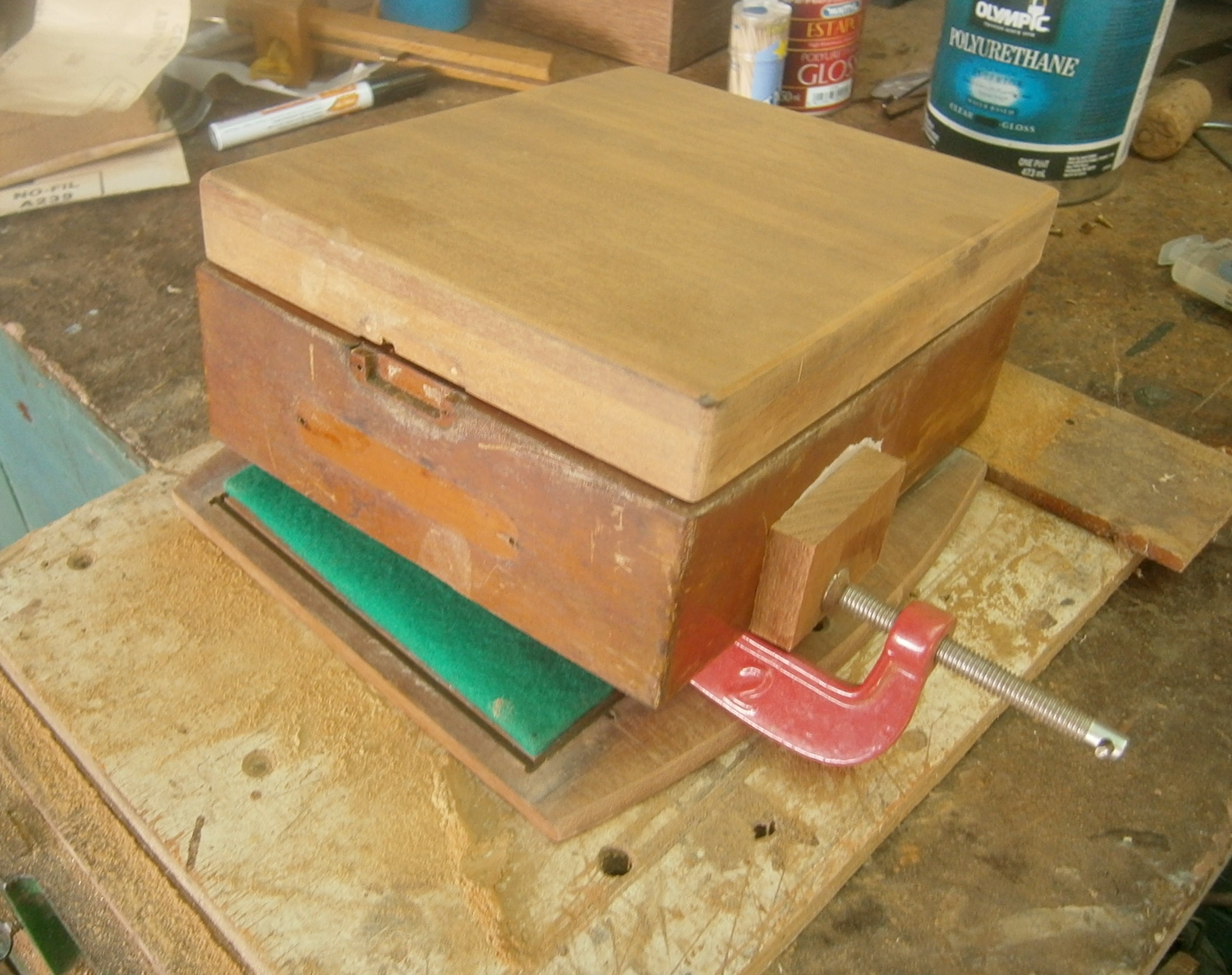
Figure 2: Repair of transport case
The base had warped and partly torn away from the sides, and in doing so, one of the nails had partly detached a large flake of wood from the side of the case. After completely detaching the the sides from the base and introducing glue underneath the flake with a flexible blade, I was able to clamp the flake back in place under a wood block with loss of only a small chip from one edge. It is possible to see that I have interposed a slip of baking paper between the block and the case, to prevent any surplus glue from sticking to the block. As all the varnish had perished, I started to remove the varnish from the lid while the glue was drying, with the result shown in Figure 2. When everything had been glued and clamped together, I cleaned up the verdigris-coated hardware, re-waxed the leather strap, gave the woodwork several coats of polyurethane varnish and re-assembled the case, with the pleasing results shown in Figure 3. The latch on the catch no longer worked and I laboriously filed up a new latch from 3 mm brass, with a slight modification to ensure that the tail of the latch remained in its guide at all positions. Happily, the inner wooden case was in good condition except for the perspex window, which was completely opaque and so brittle that it crumbled almost to the touch. I replaced it.

Figure 3: Restored transporting case.
The seller had honestly disclosed that, while the watch could be wound and the seconds hand went round, nothing else did. I was soon to find that much of the exterior of the watch case had a fine powdery coating of verdigris and the back had a dense coating of black corrosion products. While the stem would rotate, it would not move in or out, even with the safety setting button depressed. Plainly something in the setting mechanism was stuck (See Post 11, Figure 9 to 12). This was only the beginning of my difficulties as I soon found that I could unscrew neither the back nor the bezel to get inside the watch, even wearing rubber gloves to give better grip. Releasing compound applied and left over night did not help, so I had to be more inventive.
For the back, I held a block of scrap wood in the vice and stuck the back to it with a hot glue gun. Applying some brute force to the rest of the case eventually made it give up its grip on the screw-back and the glue could then be peeled off the metal. The bezel was not so easy, as a test of hot glue on a scrap of perspex showed that it fused to the perspex and could not be peeled off, so whatever solution employing glue had to keep it away from the perspex “glass”. Figure 4 is posed to show the solution I adopted. I set up a square of scrap wood in the 4 jaw chuck of a lathe and turned out a recess that would allow the glass to sit in it without being exposed to hot glue. I then ran a bead of hot glue around the metal of the bezel and brute force made it too give up its grip on the case.

Figure 4: Releasing the bezel.
The underside of the screw-on back was black with corrosion, traces of which may be seen on the upper right of Figure 5, posed to show the safe way to remove the underlying snap-on back. The index finger insinuates the edge of the blade under the back by pressing opposite the belly of the blade. Held in this way, if the knife slips, it cannot scoot across the bridges of the movement and scratch them or wreck the balance.
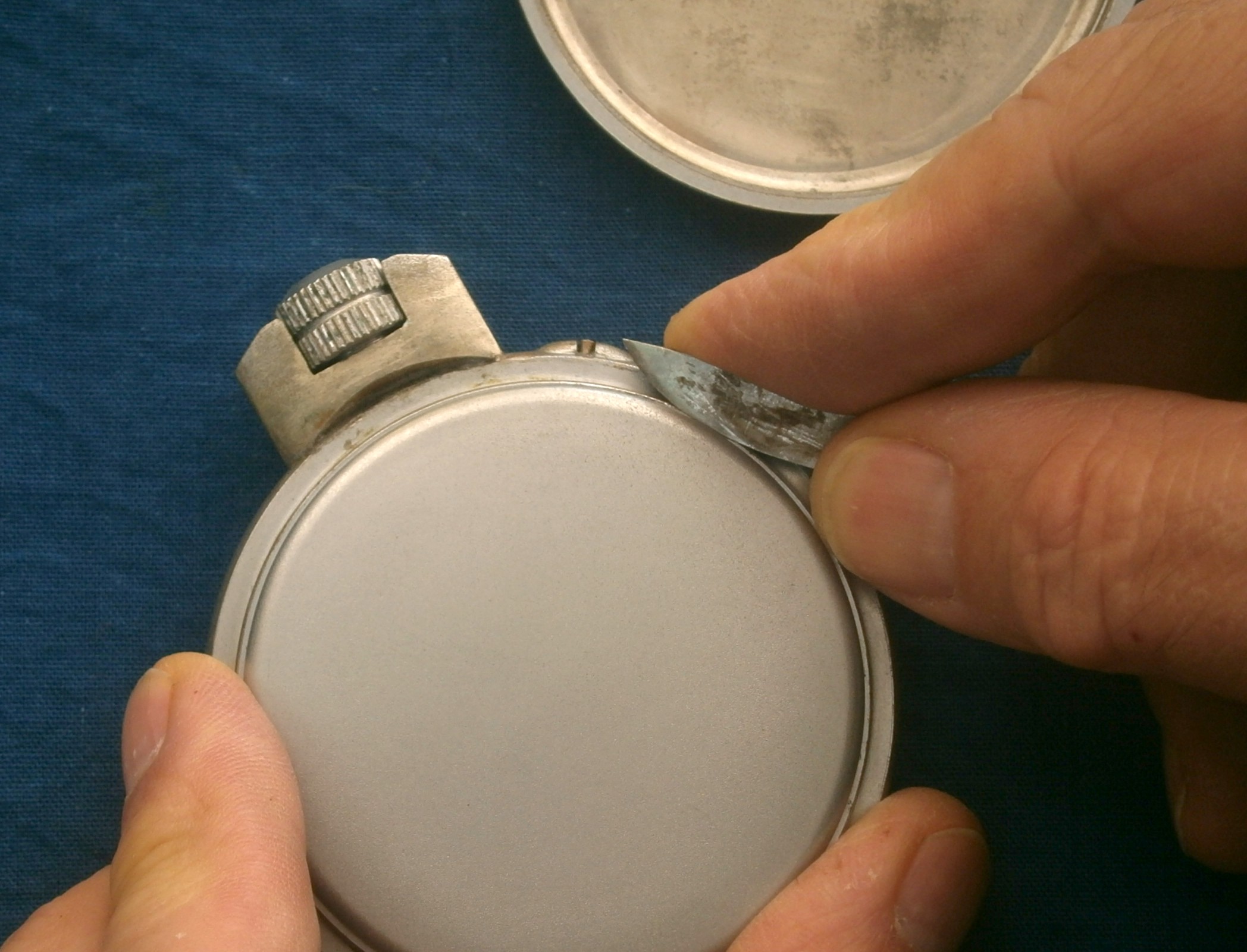
Figure 4: Safe removal of back.
This is perhaps a good point to explain about verdigris whose original meaning was “Greek green”. The body, back and bezel of the watch are made of brass, an alloy of copper and zinc, and are over coated with a dull chrome finish. The movement plates are made of nickel-plated brass. Many years of exposure to a moist, and in this case, marine, environment led to the formation of green compounds of copper, mainly basic copper carbonate and chloride. Given the right conditions the former can form black oxides of copper and it was these that formed a dense coating under both backs. Figure 5 shows the underside of the inner back where I have started to remove the black oxide physically.

Figure 5: Corrosion products under inner back.
Figure 6 shows the back of the movement after partial cleaning and trial assembly. Prior to this there was everywhere a fine dusting of verdigris, even inside the mainspring barrel and on the adjusting nuts of the balance wheel. Three screw heads were rusted as was part of the goose-neck of the micro adjuster (Figure 6)
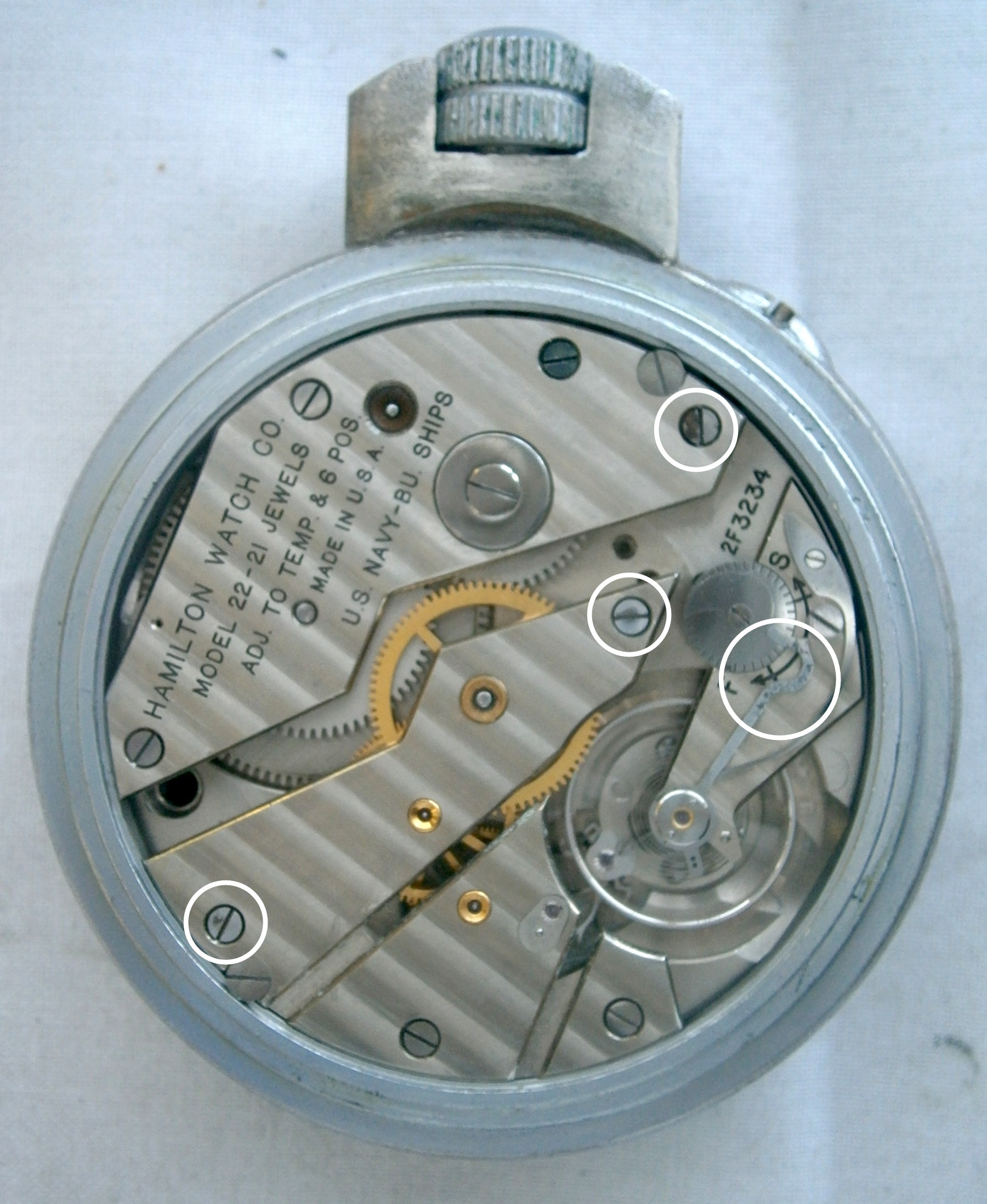
Figure 6: Sites of rust.
But this is to jump ahead, as I had first to remove the movement from its case. This could not happen without withdrawing the winding stem and I could not do this without exposing more of the movement. Certainly, backing off the blue-headed screw at just past twelve o’clock released nothing. I hoped that if I removed the barrel and train bridges I might obtain sufficient movement within the case to get at the pillar screws of the dial and thence get access to the setting and winding mechanism in order to release the winding stem, but I could not remove the barrel bridge, barrel and winding wheel without first removing the centre wheel, and I could not do that without removing the canon pinion, which of course lay the other side of the pillar plate, under the face that I could not remove. In the end I reasoned that not a great deal could happen that was irreversible, so after removing the hands I attempted carefully to pry up the centre wheel and its arbor. The canon pinion resisted hard, no doubt because of its share of corrosion, but it eventually succumbed, and at the same time a “snick” told me that the centre wheel had also partly released its grip on the arbor. Happily, I have a comprehensive staking set, so I was quickly able to re-attach the wheel and check its alignment (Figure 7).

Figure 7: Checking centre wheel alignment between centres.
With the barrel and train bridges removed, and all the associated wheels, my hope that there might be just enough movement to get at the dial pillar screws was realised for two of them, but not for the third. These screws are tiny screws that pass radially into the pillar plate and hold in place the three pillars that are attached to the back of the dial. Again I reasoned that the worst that could happen if I pried off the plate with brute force was that the third pillar might break off from the back of the plate, in which case I could solder it back into place. Fortunately, the tiny pillar screw did not have much of a grip to resist my prying, and once the dial was off, I could see all of the winding and setting mechanism.
While there was the usual dusting of verdigris, I could remove most of the parts (Figure 8, copied from Post 11), except for those pierced by the winding stem, and I still could not remove the stem so I could proceed to remove the rest of the movement. The stem would rotate but it would not slide. The clutch and crown wheel slid freely on it, so the trouble had to reside where it had to pass through the body.

Figure 8: Setting and winding mechanism.
I imagine that by now, any professional watch maker reading this will be shuddering at the anticipation that more brute force was applied, and they will be right, for I was able by using copious releasing compound and careful prying, to make the case give up its grip. After this, all was relatively plane sailing, to remove all the parts and clean them (Figure 9). Note the use of a white painted baking tray to hold the parts in order. The professional who, from long practice knows what everything is and where everything goes, will simply place them in a cleaning machine and get on with something else, and s/he can get away with setting them out on the bench and immediately assembling them. The amateur who leaves the parts on the bench will sooner or later pick something up on the shirt sleeve and lose it, or thoughtlessly rest the edge of a hand on the tiny pallet arm and break it, or the cat will explore…
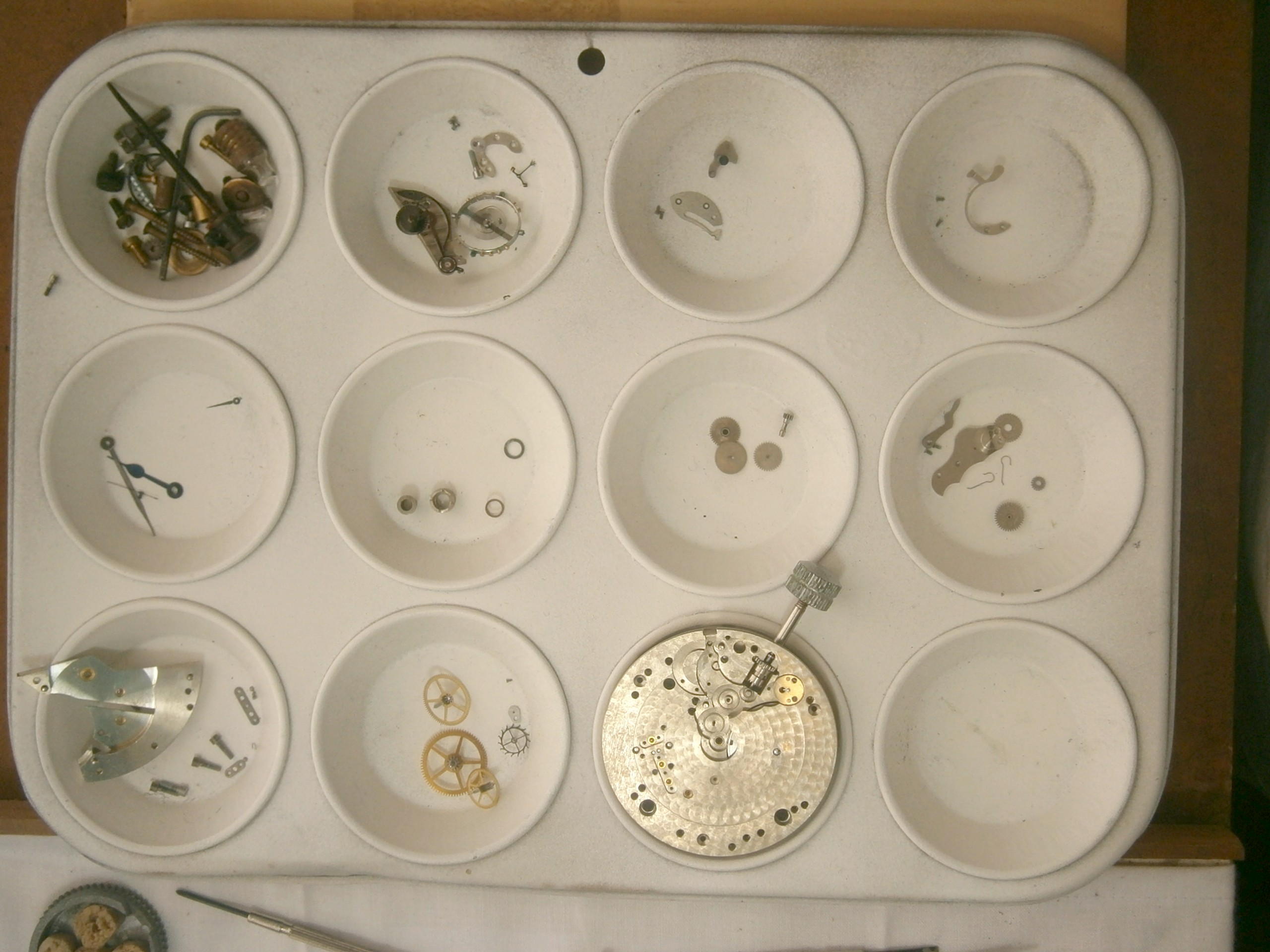
Figure 9: Parts and assemblies ready for cleaning.
I don’t have a cleaning machine and have to transfer parts of assemblies from one jar of solvent to another. In this case, the first attack was on the verdigris, for which I used a soapy solution of ammonia, in which the copper corrosion compounds are for the most part soluble. I followed this with a water rinse, alcohol (briefly for the pallets and balance, whose jewels are set in shellac), acetone (which forms tetramino compounds with verdigris) and naphtha, inspecting the cleaned parts for any traces of dried up grease and verdigris. Figure 10 shows the extent of the problem for the balance wheel. In principle, having been made of 18-80 stainless steel which does not contain copper, it should not have verdigris, but it is chromium plated, which besides being porous, is sometimes plated on to a preliminary plating of copper and nickel. The condition of a timing nut, made of brass, is shown in the inset. The compensating screws appear to be made of gold, which does not corrode in normal circumstances. I cleaned the rusty steel parts and polished them with progressively finer grades of emery paper.

Figure 10: Balance before cleaning.
I left the compensating screws, timing nuts and balance spring where they were, but dismantled everything else, removing end stones in their settings for careful cleaning and the mainspring for inspection and re-greasing. Happily, despite the verdigris within the barrel, the steel of the spring was free from damage and corrosion.
Upon re-assembly of the watch, I was delighted when it again burst into life and was not too fazed to find that it was gaining at a rate of 56 seconds a day, perhaps through loss of material from the rim of the balance and the timing nuts. The regulator, set to its slowest, could lower this rate to 22 seconds a day, but this is unsatisfactory for a watch of chronometer grade, and in any case, the official manual recommends setting the regulator to mid point and adjusting the timing screws to get a daily rate within 6 seconds, then using the regulator for closer rating. On my second attempt, having turned each nut out by 5/8ths of a turn the watch was within reach of this rate and by lucky chance, a single tweak of the regulator has achieved a negligible rate, gaining or losing less than half a second a day.
This contract for this watch was let in 1941, it was made in 1942, went to sea in 1955, and was shipwrecked in 1971. Seventy three years after its birth it is still going strong (Figure 11).
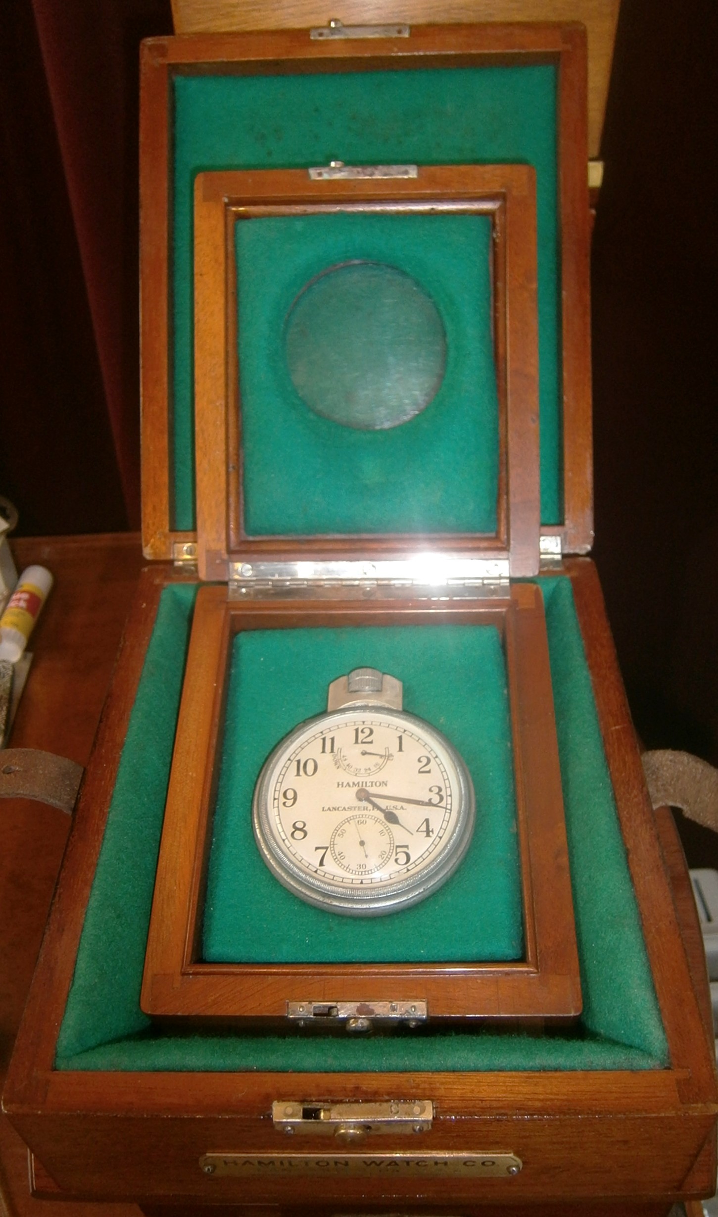
Figure 12: Ready for another 74 years.
If you have enjoyed reading this post you may also enjoy reading my books “The Mariner’s Chronometer” and “The Nautical Sextant”, both of which aim to demystify the construction and inner workings of these wonderful instruments of precision.

Congratulations on this website! It conveys what I already know…you have a very rare and special interest/ability. I have shared this website with some people I think will find it interesting, as I have.