Clicking on the figures will provide you with an enlarged view. Use the back arrow (top left corner) to return to the text.
Recently, a Kirova MX6 chronometer, which had been keeping a very good rate within half a second a day, began to have a very irregular rate, sometimes amounting up to six seconds a day, so it was plainly time for an overhaul. The irregularity could have been due to variations in power, though by now the conditions required for an isochronous balance spring are well understood. If a balance is isochronous, it means that its period of oscillation does not vary with the amplitude of oscillation. However, since the instrument plainly needed attention, I checked for causes of loss of power due, say, to a dry mainspring or rusted links in the fusee chain, but these areas seemed to be fine. I removed the mainspring and replaced the grease anyway, and checked each link of the chain for free movement. The chain too received a good clean and some fresh lubricant. The wheels and pivots of the train were also checked for defects.
When it came to the balance staff, I found one or two pieces of cotton fibre, visible only under a microscope and sticky, thickened oil which had spread from the upper balance pivot on to the shaft of the staff. After cleaning it up, it was then just possible to see with the naked eye that there was a groove in the upper pivot and this can be seen in Figure 1, which shows the isolated staff, with a scale of millimetres above, to give some idea of how it compares in size with a pocket watch staff. It is obviously much bigger and more robust, and so easier and safer to handle than the latter (you can enlarge the photos by clicking on them).

Figure 1 : Balance staff
As an aside, when examining things like staffs under a microscope, it helps to make a little jig, assembled from pieces of microscope slide, to hold the part horizontal. In the jig on Figure 1, I glued two uprights to a slide, having first filed vee notches in the uprights to prevent the staff from rolling off. Thus under control, the mechanical stage of the microscope can be used to move the slide around for systematic examination. Figure 2 shows the condition of the upper pivot with dimensions added. A pivot diameter of around 0.2 mm is common for chronometers, while pocket watches typically are under 0.1 mm.

Figure 2: Cut upper balance pivot.
Plainly, something is very wrong, as the pivot is “cut”, maybe as the result of rough handling or careless assembly causing the hole jewel to be chipped or cracked or perhaps due to defective heat treatment of the staff. However, the staff shown is hard chromium-plated and, although I could see no defect in the jewel, I replaced it anyway. For the staff there were three options of increasing difficulty: to replace the staff or re-pivot the existing one or make a whole new one, and as spare parts are still occasionally available for this type of chronometer, I took the easy way out and simply replaced the whole staff. Figure 3 shows the over-all length of the staff being checked using a bench micrometer. The dial indicator on the left is set to zero against a slip gauge, seen at bottom left, with the micrometer reading zero. When measuring a part, the micrometer head on the right is rotated until the indicator again reads zero and the reading on the micrometer head is added to the length of the gauge.
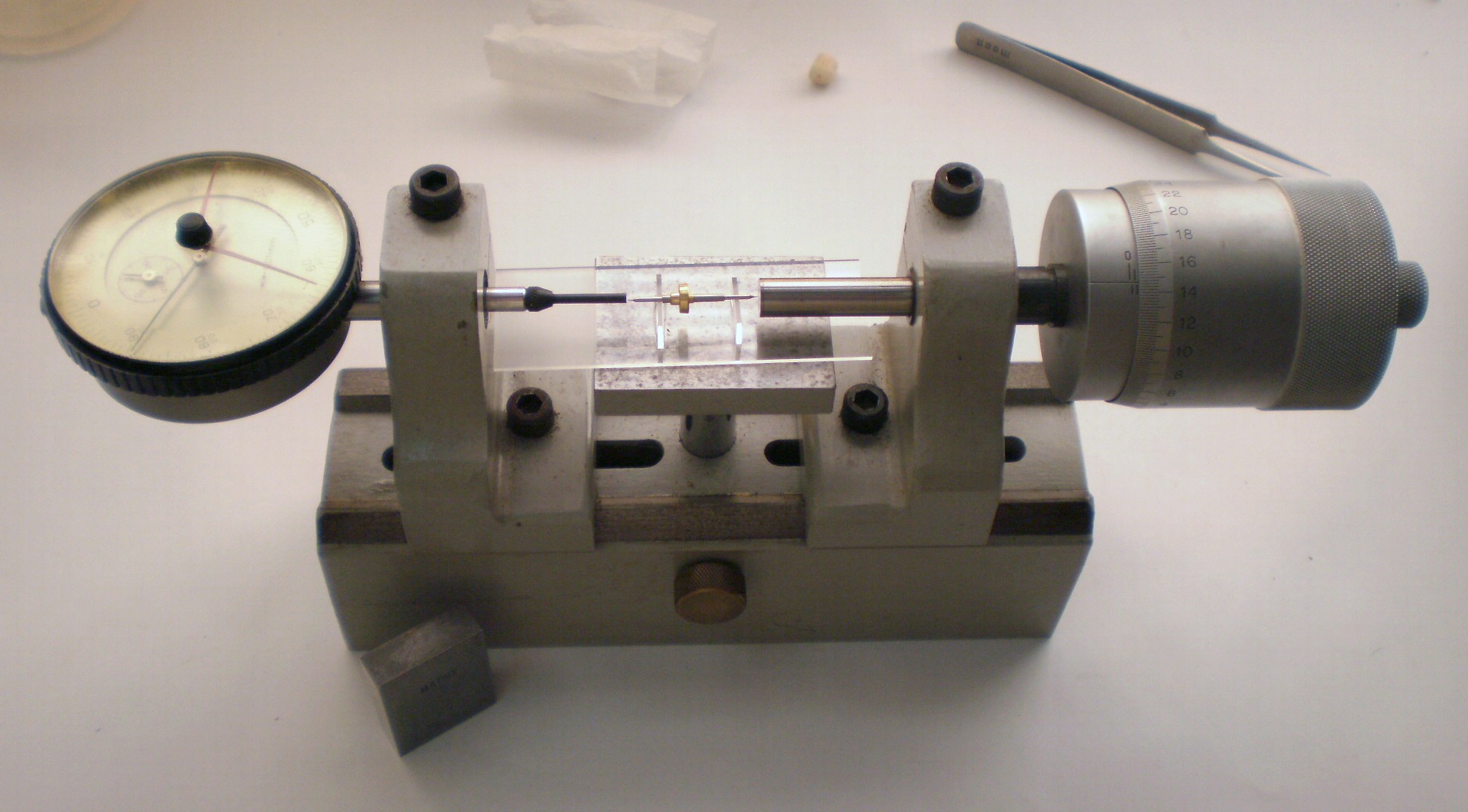
Figure 3: Checking new staff for length.
To make matters easier, it is helpful to take photographs or make sketches of the relative positions of the balance spring and the rollers so they can be replaced in the same positions. Figure 4 shows the balance from above with a line added to show the position of the upper balance spring stud. The timing nuts are at three and nine o-clock. The lower balance spring collet is split as shown at about 8 o-clock to allow adjustment. To remove it from the tapered shaft, insert the tip of a screw driver into the split and rotate it while drawing it upwards. If it doesn’t want to move upwards, pry gently from below.

Figure 4: Angular position of balance spring\
Figure 5 shows the angular positions of the discharge and impulse pallets and rollers. Note that the acting faces are radial and that the discharge pallet is much smaller and therefore it is harder to be exact about its position. The position of the balance spring stud is shown by the white line. It is about 180 degrees from the impulse pallet and the latter is about 80 degrees from the discharge pallet. The balance wheel is removed after releasing two countersunk screws and stored safely with the spring.

Figure 5: Angular positions of impulse and discharge jewels.
This then allows an approach to removal of the rollers, but first it is wise to check the longitudinal position of the discharge pallet. The end of that shown in Figure 6 is resting on the face of the impulse roller and the act of removal may cause it to jump out of its slot. It is as well to be prepared for this and perhaps save many anguished minutes looking for a tiny sliver of ruby. If it does fall out, it is a simple but ticklish job to re-shellac it into place and I will perhaps cover this in a future post. Note the flat on the roller. This makes adjustment using a close-fitting wrench easier.

Figure 6: Impulse roller and jewel.
Figure 7 shows the rollers and staff set up in a roller removal jig. That shown is simply a piece of 6 mm steel with a vee slot cut into it and the face of the vee relieved to a suitable thickness such that the vee will fit between the impulse roller and the balance wheel collet. A light, sharp tap with a hollow punch that fits over the pivot will usually cause the staff to drop out of the rollers, and it can then be put away safely to await re-pivoting.

Figure 7: Roller removal.
The balance wheel is then attached to the new staff so that the rollers can be replaced in the correct angular relationships. Figure 8 is a posed photograph without the obscuring wheel, to show how the staff is set up on a stump in a staking tool with a hollow punch pressing the rollers back into place. They should not be hammered into place, especially not the discharge collet, as doing so may split it as it is forced down the taper of the staff.
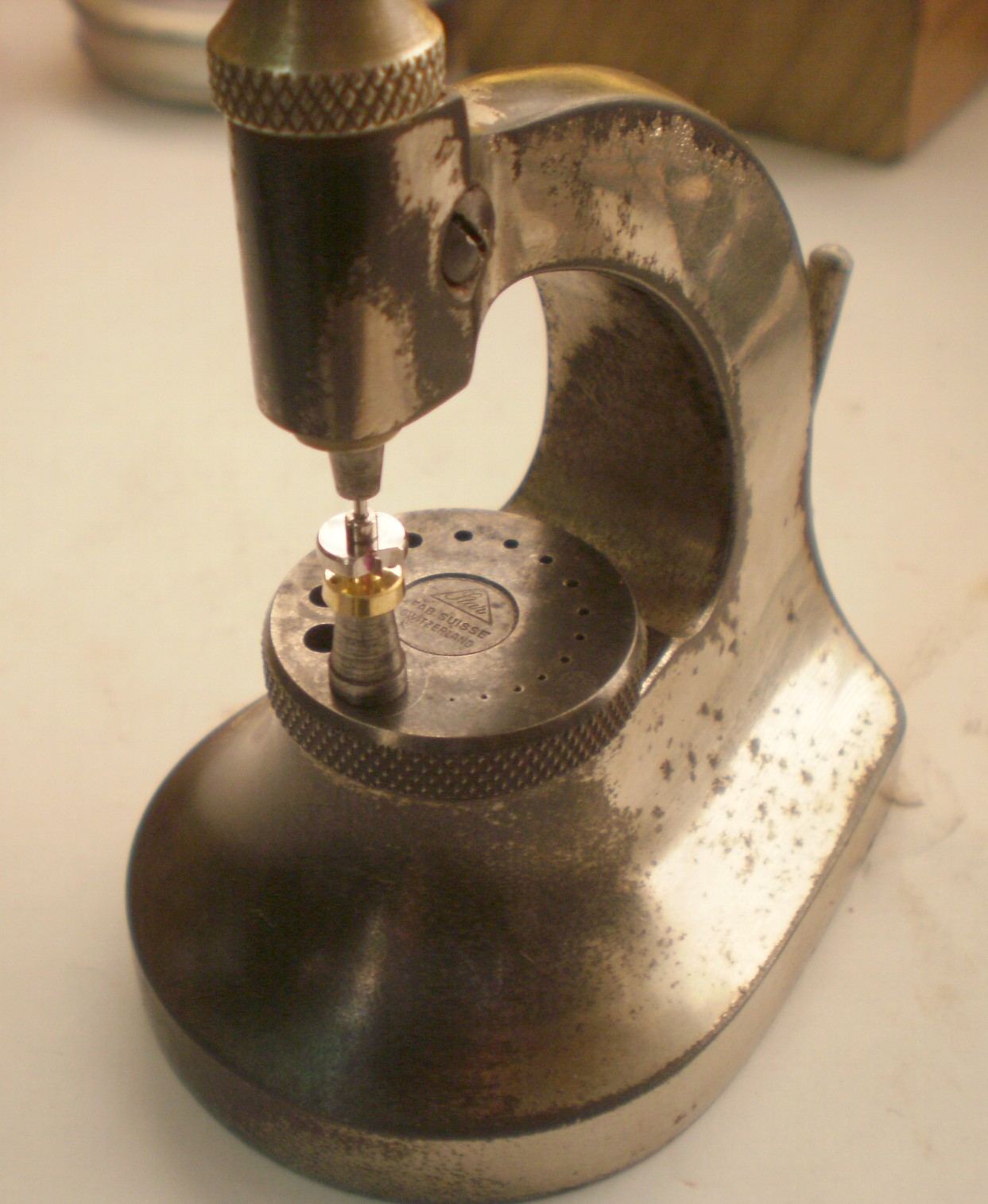
Figure 8: Posed replacement of rollers.
Once the wheel and rollers are back in place, hopefully in the correct angular relationships, the balance may be poised as shown in Figure 9. Poising is perhaps less important in a chronometer than in a watch, since a chronometer is always face up with the balance staff vertical, but it is worth paying attention to detail with such a precise machine. There is a variety of poising instruments including those with adjustable ruby knife edges on a mounting with a spirit level, but a pair of truing calipers used as shown in Figure 9 seems to serve as well, at less expense. One or other of the timing nuts (not the compensation weights) is adjusted until the wheel shows no tendency to come to rest at any particular position

Figure 9: Poising the balance.
It then remains only to replace the balance spring and refit the balance in the chronometer. At rest, according to most authorities (and there is precious little in print) the discharging jewel should be resting on the front face of the passing spring, just about to release a tooth of the escape wheel, but in the MX6 it is at rest about 10 degrees on the other side of the passing spring. Any adjustment to the lower spring collet alters its relationship to the discharge and impulse pallets. The position of the latter should be such that it and the escape wheel tooth are moving at the same speed when the tooth catches up with the pallet. If the angle is too little, the pallet may miss the tooth altogether and if it is too great, there may be insufficient impulse given.
Details of the action of a chronometer escapement are given in great detail in Chapter 2 of The Mariner’s Chronometer and some advice about its adjustment is in Appendix 1. I may attempt a systematic account in a future post. An alteration to any part of the escapement affects other parts and it is easy to go around in circles.

Recent Comments