A little over two years ago I wrote on how I set about making a spring detent for a Soviet era MX6 chronometer by using mainly machining methods (Post 22 of 20th June 2016). I had to make the spring by filing and, after re-reading an account of how V.E. Van Heusen had mass-produced detents for the Hamilton M21 chronometer during WW II* it occurred to me that it is very unlikely that he produced the springs by filing. Indeed, it seemed to me that the only practicable way of making the springs in qualtity was by surface grinding. This involves passing a rigidly held workpiece beneath a grinding wheel and decreasing the distance between them by finely controlled increments until the desired thickness is reached.
The design of the M21 detent is such as to make this relatively easy, as it is feasible for one side of the spring to be supported while the other side is reduced to the correct thickness (Figure 1). This is not true of most spring detents, including that of the German Einheits-Chronometer (Figure 2) and the Soviet MX6 which is a very close copy of it.
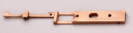
Figure 1: Part-finished M21 detent (Courtesy of Tim White).
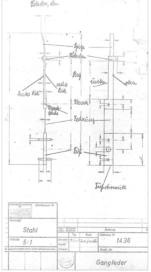
Figure 2: Drawing of Einheits-Chronometer detent.
Figure 3 shows a sectional drawing of the MX6 detent rather more clearly. If one side of the spring is ground and the detent is simply turned over to grind the other side and reduce it to thickness, the spring is unsupported in the middle part so is likely to flex against the cutting forces.
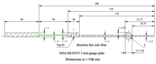
Figure 3: MX6 detent section. Spring (green) not to scale.
A few weeks ago, I set out to see if I could produce a detent with a spring ground to size and emulate manufacturers who presumably did not have an old gentleman sitting at a bench patiently filing away day after day, at least not in the 20th century. The problem resolved itself into producing a simple jig to hold the machined detent securely while each side of the spring was ground. Figure 4 is an un-dimensioned drawing. For those not used to seeing engineering drawings, the top drawing is a plan view and the bottom a side view. The surface destined to support the spring I have shaded in green and the slot to accommodate the pipe of the detent is in red.
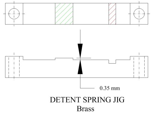
Figure 4: Jig drawing.
It is a simple matter to make the jig, starting by milling the bottom flat, drilling the two fixing holes and securing it to a hunk of cast iron that has been ground flat and parallel on both surfaces. Then the top is machined all over. When milling the detent I had left the bottom surface of the spring a measured 0.35 mm below the level of the foot and taken 0.2 mm off the top surface, leaving an allowance for grinding of just under 0.2 mm, about the maximum that could be milled without distorting the spring, which was supported only at the ends and one side. Thus, after milling the top of the jig, I had to lower the cutter 0.35 mm to do the rest, followed by a further 1.5 mm to cut the slot for the pipe. Figure 5 shows the jig against the partly milled detent, still attached to its parent metal.

Figure 5: Jig against detent-to-be.
Once freed from its parent metal it was a simple matter to attach the detent to the jig with flake shellac, by heating the jig on an upended domestic iron, melting on some shellac and holding down the detent while the shellac cooled (off the iron, of course). I had hoped it would be a simple matter then to screw the jig to the cast iron block, trim a grinding wheel to a thickness of 5 mm and gradually reduce the spring to a thickness of 0.08 mm (Figure 6). It was not to be, as my horrible old Indian surface grinder refuses to do anything other than stick and slip when putting on cut, so my first attempt led to complete disappearance of the spring as a cut, put on by measuring with a dial gauge, suddenly increased as I passed the detent under the grinding wheel.
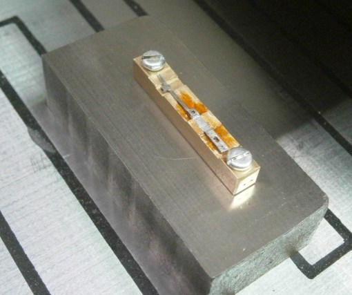
Figure 6: Jig on surface grinder chuck.
After remarking to myself how very unfortunate that was, I set about making an adapter to attach a small grinding head from my home-made Quorn tool and cutter grinder to the spindle of my light vertical milling machine, which has fine control over down movement of the quill. Making the adapter was a relatively simple turning exercise, but locking the spindle against rotation was not. However, I eventually succeeded, but in a moment of carelessness put on too much cut and ended with a spring a mere 0.02 mm thick. As making a detent involves annealing the metal to remove locked-in strains, and cutting and truing up a blank, before the detent can even begin to take shape, it takes me about three hours to mill one to shape, so I decided to leave grinding for another day.
However, it did occur to me that the jig would allow me to hold the detent more securely when filing the spring, using my swing tool, so I made one more detent, which gave me an opportunity also to practice polishing. Figure 7 shows it in the swing tool. If you compare it to Figure 9 in post number 22, it will be apparent what I mean.

Figure 7: Jig in swing tool.
I am fairly sure that the procedure I have worked out to grind the spring is a workable one, and getting control of the grinding head downward movement is the nub of the problem, so I have not entirely given up the idea. It also occurs to me that attaching the jig to a piece of flat plate and screwing two hardened filing guides a few cm either side might allow reliable spring production by those without swing tools. Meanwhile, I have a spare detent, though it is not for sale… (Figure 8).
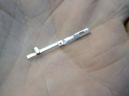
Figure 9: Finished detent.
There may well be machinists reading this who have much greater skill than I have and who may have faced and solved similar problems in the past. I hope they will not hesitate to contact me to put me wise.
*NAWCC Watch & Clock Bulletin, January/February 2012: The Man Who Saved the Hamilton Model 21 Ship’s Chronometer.

Leave a comment