In the 1930s marine chronometer production in Germany was centred on Hamburg and Glashütte-bei-Dresden. German watchmaking had originated in the small town of Glashütte and by 1934 was in difficulties. The armed forces had been a significant buyer of high-class chronometers prior to the First World War, but the loss of the German Navy following the war had led to a sharp decrease in demand. The town Council proposed a programme to make 500 instruments over five years and in July 1935 a meeting was held in Berlin involving the ministries of war, transport, education and aviation, with input from the mechanical and optical manufacturers and Deutsches Seewarte (the German Naval Observatory).
This led to the German armed forces being directed to survey their holdings of chronometers and to their scrapping about 65 percent of mainly English chronometers. Arthur Lange and Son developed their Normal-Chronometer, a classical marine chronometer with spring detent, fusee and chain. This gave way in about 1940 to the design of the Deutsche-Einheits-chronometer or German Standard Chronometer which went into production by Gehard Wempe of Hamburg, who had taken over Hamburger Chronometerwerke GmbH from the ship builders of the city in 1938. Wempe began production of the Einheits-chronometer in 1942 in association with A Lange and Son. Production of parts was divided between the two firms. In all, about 2750 were made, presumably with serial numbers not starting at 1, as I am the guardian of number 3018.
At the end of the Second World War, Glashütte was under Soviet control and was obliged to make 250 chronometers for the Soviets as reparations, as well as providing a full set of drawings for the Einheits chronometer, which allowed production of the identical Soviet MX6 in Moscow. Then chronometer making was resurrected in 1951 in a nationalised firm termed VEB Glashütter Uhrenbetriebe (People’s Clock-making Company), formed mainly from A. Lange and Son and Mühle and Son. This company resumed making chronometers to a pre-war design which differed in a few respects from the Einheits-chronometer and the Soviet MX6. Production ceased probably in 1978, before re-unification of Germany. Early dials gave the full information shown in Figure 1, while later ones had simply Glashütte in the centre (Figure 2) though the GUB stamp continued to be marked on the upper plate.

Figure 1 Early face.

Figure 2: Later dial.
I was able to buy an example in a very poor and dirty condition, not going and for a relatively modest price. Figure 3 shows the condition of the plates as found…

Figure 3: Condition of the plates as found.
…while Figure 4 shows the state of one of the balance pivots. Everywhere, the oil had dried to the consistency of a hard soap.

Figure 4: Dirty balance pivot.
Careful cleaning of the plates resurrected them enough to make the maker’s mark readable on the top plate (Figure 5). In restoring the much corroded and scratched plates, I tried to compromise between removing scratches and preserving the once-beautiful decoration. Practically all makers decorated the plates in some way, even in times of war, and even though they would normally only be seen at overhaul by the chronometer maker. This was true of the Einheits-chronometer, even when economies were being made by making the bowls of black Bakelite.

Figure 5: Maker’s mark (GUB Glashütte/SA).
Figure 6 shows the completed cleaning. I was not able to remove some stubborn finger prints without risking the decoration.

Figure 6: Cleaning completed.
The Einheitschronometer and MX6 had only three pillars with their positions shown by white circles in Figure 7, whereas the GUB version and its pre-war predecessor had four. The position of the extra pillar is shown by a black circle and Figure 8 shows on the left how the attaching screw also secures the barrel plate. In the other chronometers, the the top plate is threaded for screws that attach the barrel plate to it.
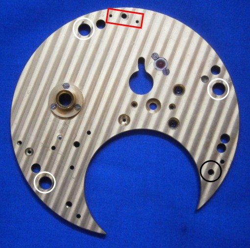
Figure 7: Position of pillar holes (MX6).

Figure 8: Pillars of GUB chronometer
During WW II, some German chronometers were fitted with a steel band made by Sandvik of Sweden instead of the traditional chain. I have alluded to possible reasons for this in Post number 27, in which I describe substituting flexible steel cable for a chain. It is possible that in post-war East Germany, the craft skills for chain making simply did not exist. The band, 730 mm between the bights of the hooks, is shown in Figure 9, and is approximately 0.2 mm² in cross section.

Figure 9: Driving band and hooks.
Figure 10 shows the band in place on the barrel. Fitting it can be difficult as, unlike a chain, it cannot simply be wound on to the fusee and left there prior to attaching it to the barrel, on account of its springiness. It has to be wound on to the fusee with the latter in place between the plates and, while maintaining tension on it, the barrel is put into place, the hook attached and the barrel rotated to take up the tension and its click engaged. Before working out how to fit the band, I despaired a little and instead fitted a chain, only to find that the height of the chain meant that it fouled a head of the screw that attaches the stop work to the top plate before the final turn. As a result, the chronometer could be wound only to 48 hours instead of the usual 56 hours.
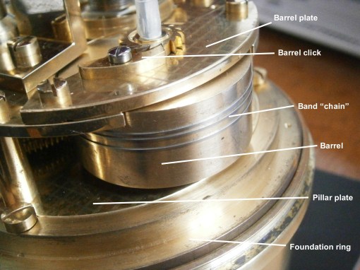
Figure 10: Driving band in place.
The stop work for all but very early Einheits-chronometers and the MX6 is incorporated into the top of the fusee in the form of a transverse rectangular bar which can slide out of the fusee against a spring load. As the chain reaches the top of the fusee, it presses on one end of the bar to make the other end of the bar project, and this end then encounters a stout pin projecting from the underside of the top plate, bringing winding to a halt.
The GUB chronometer, however, uses Geneva or “star wheel” stop work, which is shown exposed in Figure 11. As the fusee rotates, a pin projecting from its top engages with the star wheel and makes it rotates through part of a revolution until eventually it buts against the part where there is no gap between the “teeth” and prevents further rotation. A leaf spring prevents unwanted rotation due, say, to vibration. I have illustrated a slightly different form of this mechanism in Figure 7 of Post number 20.
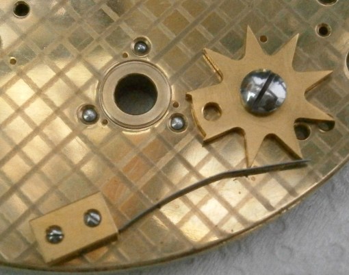
Figure 11: Geneva stop work.
Figure 12 shows the stop work in place and the screw head that prevented the final turn of the fusee. When fitting the driving band, and before fitting the top plate, the star wheel should be rotated so that the fusee can engage with a gap in the wheel and so that fusee can make all its turns. The top plate is then assembled, the fourth wheel blocked and the fusee hook engaged with the fusee, which is then wound while feeding in the band under tension, as described above.

Figure 12: Stop work in place.
I found the detent a little difficult to fit, as the foot of the support block lies partly behind a pillar (Figure 13), unlike the other chronometers where the foot is clear of the the pillar, as shown boxed in red in Figure 7. I found it easiest to invert the movement so the top plate is horizontal and then to tease one steady pin of the support block into place, having first roughly aligned the axis of the detent with the balance staff and rollers. Another difference in the detent is that it cannot slide axially on the support block, as its steady pins engage in holes rather than in a slot, meaning that the depth of engagement with the discharge roller is fixed.
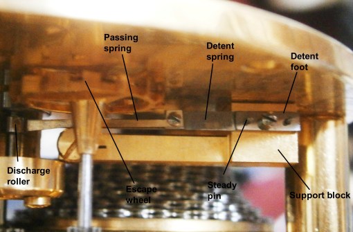
Figure 13: Detent.
The chronometer reached me with only the bowl and gimbals. The finish of the ring and brackets is very good compared to that of the MX6, which is, to borrow the words of an Australian friend, a little agricultural, referring to the finish of agricultural machinery.

Figure 14: Bowl and gimbals
As there was no case, I had to make my own from a very battered old desk, using a mixture of MX6 and home-made brass furniture. The corners have mitre joints which are relatively weak, but when provided with keys and using modern glue, they are almost indestructible (Figure 15).

Figure 15: Cross section of keyed mitre joint.
The final result is shown in Figure 16. These chronometers were not brass bound, nor were they supplied with a top lid, which often were in any event removed and lost. The pivots of the balance staff on close inspection, were slightly worn and the upper pivot of the escape wheel was broken. I elected to accept the former and repair the latter using a muff, but found the rate irregular, sometimes to the tune of two seconds a day, so eventually I bit the bullet and made a new balance staff. So far, the variation in rate seems to have improved.

Figure 16: Chronometer in its case.
I found Das Deutsche Einheits-Chronometer (Altmeppen, J. and Dittrich, H., Kinnigswinter, 2012) very informative on the history of Glashütte and highly recommend it as a source of information, even for those who, like me, struggle to read German.

Recent Comments