A few days ago I received what looks like a chronometer but isn’t. It has a face that says it came from the Hamilton Watch Company, Pa, it has a seconds dial at 6 o’clock and a “wound up/down” dial at twelve. However, the movement was made by Fema, a London firm and the escapement is a good quality Swiss lever one. In WWII many navigational watches were made by Hamilton and they performed as well as many chronometers, while in Germany, some chronometers were fitted with lever escapements for use by the Luftwaffe, so it remains to be seen how the new “chronometer” will perform. In addition to much dust and the occasional insect remains found in the movement, the dial was in poor condition with many scratches showing the brass through a heavy coat of silver, so I elected to re-silver the dial.
The first step was to strip off the old silver and the easiest way to do this, which also gives a nice clean brass surface for the subsequent coating, is to abrade it. This is best done wet, as it stops the 240 grit emery paper from clogging. I immerse a flat sheet of Paxolin in some water (but 6 mm plate glass would do just as well) add a few drops of dish-wash liquid and place a sheet of emery paper on top. It is then just a matter of carefully rubbing the dial, face downwards of course, over the paper with light pressure. Traditionally, the face was given a horizontal grain, but in twentieth century chronometers the practice seems to have fallen into disuse. I keep to up and down so that there are no circular scratches or swirls that then have to be laboriously removed later. Once all the old silvering has been removed , a few strokes on 800 and then 1200 grit paper give a very fine surface to which the silver will hold very nicely.
The surface is also very clean, so the dial should now be held only by the edges while it is heated up. I use an old electric iron for this and invert it in a vice. Sealing wax, the traditional material for filling in the chapter rings etc. , is getting harder to find, but I have a precious stock of deep blue wax to which I have added black pigment. Figure 1 shows the dial nearly obliterated by the black sealing wax. Nearly as good is Araldite loaded with some black pigment. I have used some black tile-grouting stain left over from a bathroom renovation that took place so long ago that I can no longer visualise the bathroom that needed black grouting, but the wax seems to give a better finish and anyway, it is more fun. There is no reason why gloss acrylic paint should not be used. The Araldite and paint methods do not of course need the dial to be heated…
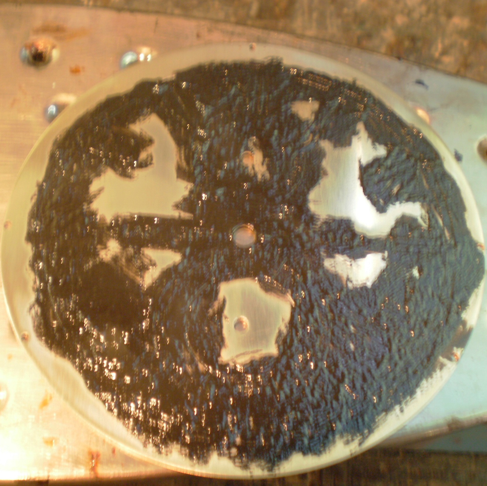
Figure 1: Filling with sealing wax.
As soon as the dial is hot enough to melt the wax, it is spread rapidly, taking care that the dial does not get hot enough to make the wax bubble. The iron can be adjusted to the right temperature. Then using a soft scraper, like a wooden iced lolly stick, scrape off most of the wax to leave the chapter rings, letter and numerals outlined as shown in Figure 2.

Figure 2: Surplus wax scraped off.
The remaining wax is then abraded off as before, to leave a clean surface for the silver. The ingredients for silvering are available from horological suppliers. I use one called Horosilv, which I believe is silver chloride, which is then fixed with sodium potassium tartrate. A damp cotton ball is dipped into the silvering powder and rubbed on the dial with a circular motion until the yellow of the brass turns to the matt white of silver. If the brass is really clean, the process takes no more than a few minutes. Figure 3 shows the process half-completed on an orphaned Mercer dial.
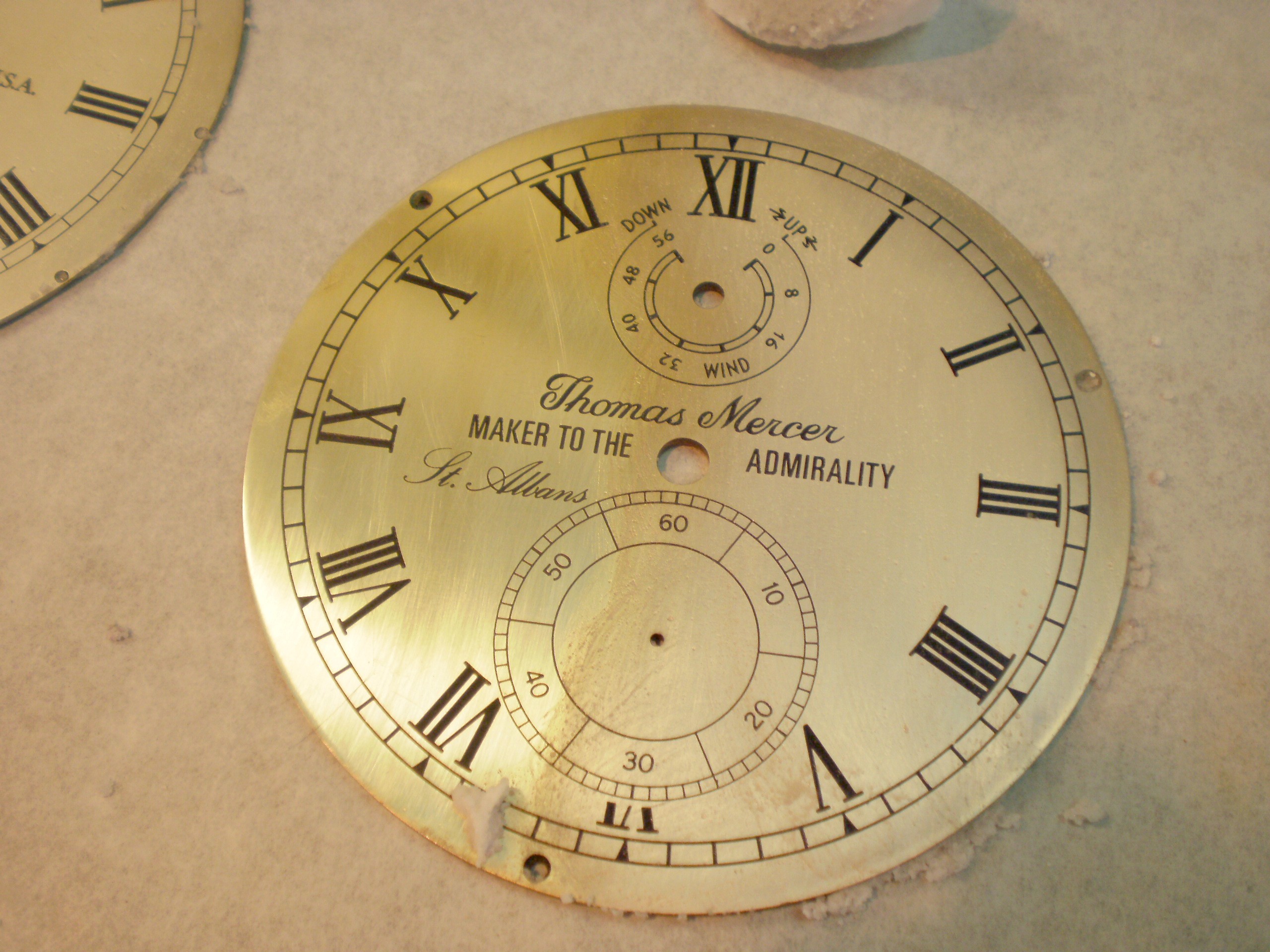
Figure 3: Silvering half completed.
Once the silver shows a uniform coating, with no hint of yellow, the silvering powder is washed off and a thin paste of the fixing powder rubbed on, again using a cotton ball with a circular motion. This is then washed off and the dial patted dry with a soft cloth. Figure 4 shows the end result. the difference in colour of the two dials is due simply to the lighting. To get a really good finish, the dial may be heated until the sealing wax just starts to melt, when it becomes shiny. It must not be overheated as then bubbles may form and the job will have to be repeated.
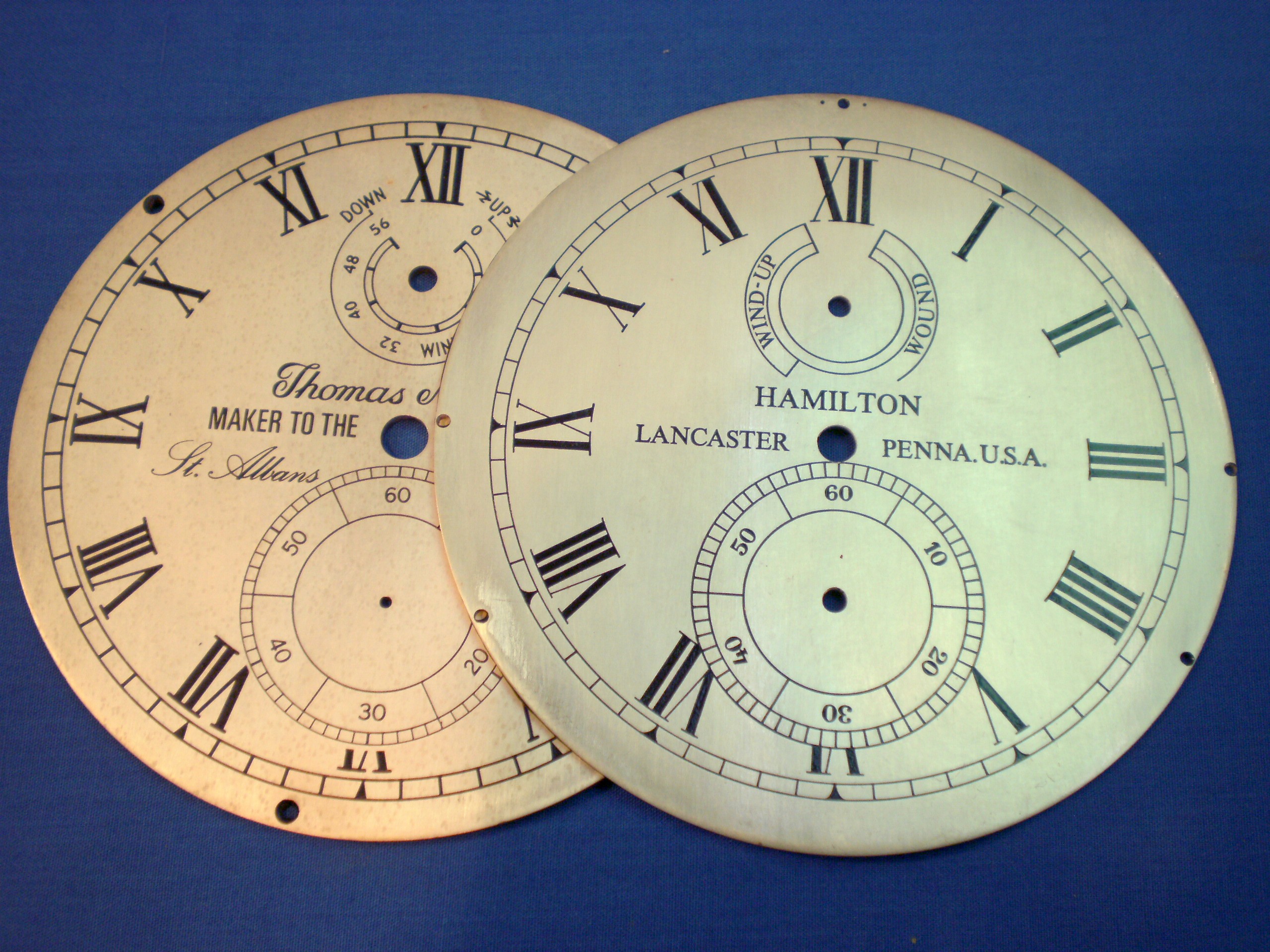
Figure 4: Silvering and fixing completed.
I live 200 km from the nearest industrial area, so tarnishing of the silver is not a problem for me. Traditionally, the silver was lacquered, but getting a good finish is a craft skill that I have not yet acquired. Again, the dial needs to be warmed gently and the lacquer sprayed or brushed on evenly. An alternative that works with Araldite and paint fillings is to apply silicone wax polish, but the solvents in such polishes may dissolve sealing wax so that the silver gets faintly stained with black when the wax is rubbed off. This has certainly been my experience. It is no disaster if it happens, as to repeat the process is so quick and simple.


Recent Comments