In Post number 5 I showed how to replace a damaged balance staff and in this post I show how to re-pivot the badly cut staff. Figure 1 shows the pivot together with its dimensions.

Figure 1 : Cut pivot
The traditional way of re-pivoting would use a lathe with the staff held in a collet and the staff steadied using a Jacot tool. A graver would be used to turn off the damaged portion and a centre for a drill started using the point of the graver. A hole would then be drilled using a spade drill and a slightly tapered piece let into the hole until it jammed in place in the hole. The pivot could then be cut off to length and finished to size using a graver. This process has scarcely changed in two hundred years, but small machine tools and their attachments are now much better constructed than they were even fifty years ago and it seems to me that we should take advantage of advances. In any case, I am nearing the end of my days and have not the time to learn skills which have been made largely obsolete by modern tools. Professionals who read what follows may disagree with my method, but it does use the skill that has been built into the lathe and employs the lathe slides that can guide a tool far better than I could by hand. It is important, however, that the cutting edge of the lathe tool should be exactly on centre height and this is best achieved by making trial cuts on a piece of pinion wire, closely observed with a magnifying lens.
The first step is to soften the end of the staff by heating. To prevent the heat from travelling too far from the end, it is convenient to hold the staff in a small tool-maker’s clamp as a heat sink and to pass the end of the staff briefly through a gas flame until tempering colours have made their way 3 or 4 mm down the staff. By clicking on the figure to enlarge the image, these colours can be seen in Figure 2 , which shows the staff held in a modern collet chuck and steadied in a home-made Jacot tool (most Jacot tools were made for watchmaking and are too small to accommodate a chronometer staff). The latter has a variety of holes of different sizes drilled very accurately on the centre line of the lathe.

Figure 2 : Facing end of staff.
Once the end of the staff has been faced square using the cross slide of the lathe, the Jacot tool can be replaced by a drill chuck and a centre started. Even the smallest standard centre drill is too large for this task, but modern small solid carbide drills are ground by the four facet method and so are self centring. I used a relatively large 1 mm diameter drill to remove the merest shaving from the centre to provide a true start for the smaller drill to follow (Figure 3). If this step is omitted, the end of the smaller drill is liable to wobble about off centre and eventually break off.

Figure 3: Centring end of staff.
Once a true start has been made, the smaller drill can follow, in this case of 0.45 mm diameter , as shown in Figure 4. A very delicate touch is needed. Marvin Whitney recommended holding the drill between the fingers in a small pin chuck, but if care is taken to keep the drilling under constant observation with a magnifying glass and to frequently withdraw the drill to clear away swarf, the normal feed arrangement provided in the tailstock can be used safely. A depth of three to four drill diameters should be deep enough.

Figure 4 : Drilling to size.
A start can now be made on the insert. Whitney recommended English sewing needles whose temper had been drawn to a “wine” colour. This corresponds to a temperature of about 280 degrees Celsius, a little lower than for normal pinion wire which tends to be blue and therefore a little softer. However, English darning needles are hard to come by so I used Swiss pinion wire, hardened and re-tempered to a dark purple (wine?) colour, turning it down to fit the hole drilled in the staff (Figure 5).

Figure 5: Turning down pinion wire.
Modern industrial adhesives have made interference fits almost a thing of the past. I used Loctite to secure the new pivot in the hole and after letting it cure, returned to the set-up of Figure 2 to turn it down to length and diameter, followed by burnishing. This is a finishing process which, as well as smoothing and polishing the pivot, to some extent may also work harden it (I seriously doubt that work hardening takes place at the pressures possible). A glass-hard burnisher is drawn across emery paper to make very fine transverse grooves and the burnisher is then pressed on to the pivot and drawn across it as it rotates. The pivot has to be supported while this is being done and my home-made Jacot tool is provided with a disk which has a variety of semicircular and vee grooves cut into the periphery (Figure 6). Prior to burnishing the end, I rounded it using a fine file. Note the use of a ball race to support one end of the burnisher and to keep it parallel to the axis of the workpiece. It then remained only to polish off the tempering colours from the staff, purely for cosmetic reasons
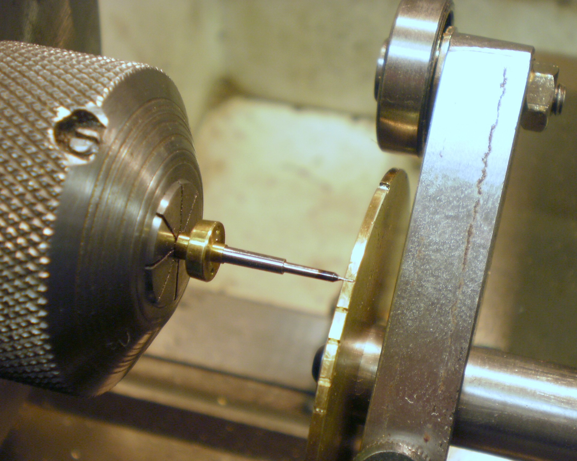
Figure 6: Support for the pivot while being burnished.

Leave a comment