Nearly all chronometers were supplied with a three tier case, incorporating a base, a hinged glazed lid and a hinged cover for the glazed lid. On board a ship, the chronometer was often mounted beneath a glazed part of the chart table so that the time could be seen at a glance. Where more than one chronometer was carried, they were mounted in a special case with a single lid for the (usually) three instruments. This meant that the cover for the glazed lid was superfluous and it was usually removed with its hinges and eventually lost. The lid was usually provided with brass corners. This seems to be due to tradition rather than necessity, since a chronometer was handled so carefully that it had no need of protection, unlike the nautical sextant which often was and the case of which was never provided with brasswork.
The present-day lover or collector of chronometers may wish to replace the missing lid, so this post gives some details of dimensions and shows how brass corners are made. Chronometer cases were usually made of mahogany, rosewood or lesser timbers stained to look like them. I have a precious supply of well-seasoned African sapele, but beech or birch can be stained to look similar. Figure 1 shows the structure of a typical lid with dimensions which seem to be pretty much the same whoever the maker, but it is as well to check against the box itself (All the figures can be enlarged by clicking on them. Use the back arrow to return to the text.).
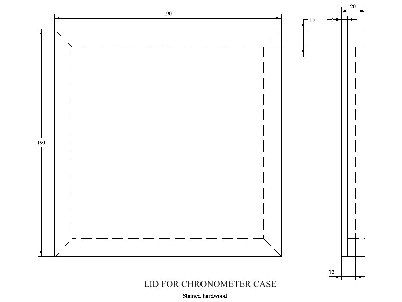
Figure 1: Dimensions and structure of lid.
The lid is in two main parts, a top 12 mm thick and a frame 15 mm thick rebated and glued into the underside of the top to give a total thickness of 20 mm. Figure 2 shows the underside of the lid to make this a little clearer. I use a simple mitre joint at the corners but those with more complex wood-working equipment may chose something more complex.

Figure 2: Underside of lid.
Brass corners made by simply folding thin sheet do not have crisp edges and look amateurish, while most of those that I have seen for sale are not correct to form. The metal workers of the past would have filed a 90 degree groove in the brass sheet nearly all the way through prior to folding the sheet to a right angle and running solder into the groove. There is no reason why this should not be imitated today, starting with a saw cut to locate and guide the file along the correct line and, since the result will be out of sight, all manner of scratches and false starts can be made as long as the resulting fold is in the right place and looks crisp. I find it much easier to use a shaping machine and to mark out all four corners on a single sheet of brass so that it is easier to secure on the work table of the machine. Figure 3 shows the dimensions of a single corner and Figure 4 below it shows a groove being cut in a piece of 1.5 mm brass sheet which has been marked out for two sets of four corners.
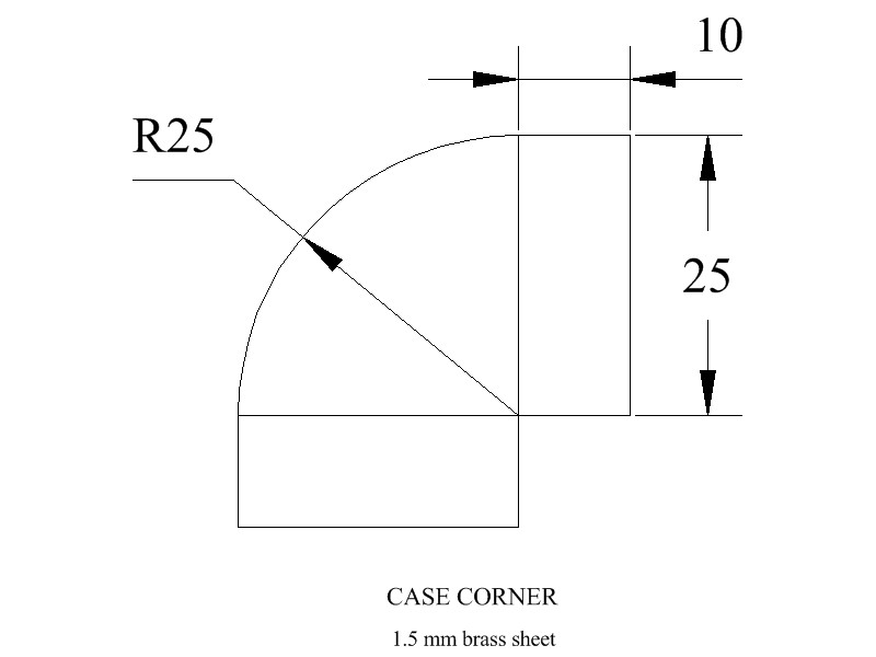
Figure 3: Dimensions of a corner.

Figure 4: Machining grooves.
The tool moves backwards and forwards, cutting on the forward stroke and deepening the grove with each stroke. Care is taken not to cut all the way through. I usually leave about 0.1mm uncut. The point of the tool is formed to an angle of 92 degrees so that when the metal is folded, the slight spring of the residual metal in the bottom of the groove results in an angle of 90 degrees and also leaves a little space for the solder to run into. Once all the grooves have been cut, the curves can be sawn nearly to size and the four corners separated prior to removing the little squares of material at the centre. Figure 5 shows me using a piercing saw to separate the corners. Note that the saw is tilted forwards a little, as this seems to make sawing in straight lines easier, but when sawing curves, the blade must of course remain vertical.

Figure 5: Separating the corners with piercing saw.
The curves may now be filed to the finished shape, either by simply filing to the marked line or, more easily, using a “cheater”. This is simply a piece of steel of the required form that can be clamped to the work piece to guide a file. Figure 6 shows one in use. When filing brass, a very sharp file is needed and one that has been used on steel will cut brass only with difficulty, so a deft touch is needed to sense when the file has cut all the brass and is sliding over the steel without cutting into it. Notice the yellow tape on the handle of the file to remind me that it is to be used only on brass.

Figure 6: Using cheater to guide file.
Figure 7 shows corners at various stages of formation, from bottom to top, cut out, cleaned up with square cut out, and folded ready for soldering. When cutting out the square, care must be taken to leave a little metal for cleaning up with a small file, so that a nice clean mitre is left at the corner without any line of solder showing. Once the folds have been made, check that the sides form right angles with the tops and with each other. Solder can then be run into the joints as shown in Figure 8.
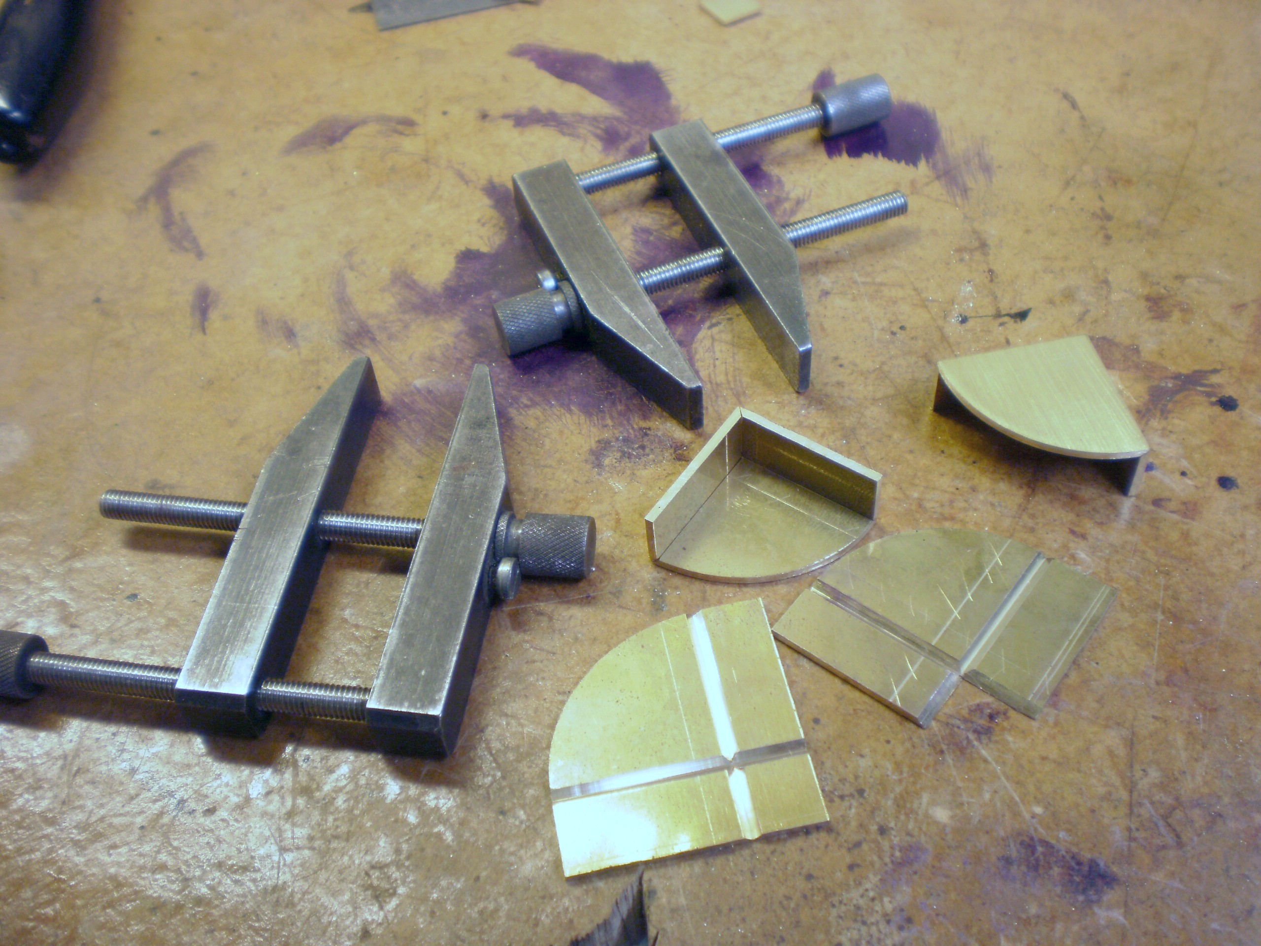
Figure 7: Stages in forming corner.

Figure 8: Soldering joints.
Seats for the corners must now be cut into the top of the lid. The rebates for the sides of the corners are relatively simple, though a sharp chisel is needed for cutting across the grain and care must be taken not to cause large splits at the end of the cut when doing so. Small blemishes do not matter, as the corner will conceal them. The cut-out for the curve, however, is more difficult and requires a chisel of the right curvature. Gouges of this size are expensive, especially if they are unlikely to be used again, so I made a rough chisel out of a scrap of steel and case-hardened the business end. Note that the bevel of the chisel must be on the inside of the curve. Figure 9 shows the cut made by the chisel and this provides enough guidance for a fairly narrow chisel to remove the waste wood.

Figure 9: Chisel for cutting curves.
Figure 10 shows the rebates finished ready to receive the corners, but first the wood must be stained and varnished to a similar finish to the rest of the case, Originally, the corners were pinned into place with narrow brass pins whose heads were then filed off flush, but a modern gap-filling adhesive such as a two-part epoxy like Araldite makes this unnecessary. Note that the corners of the rebates must be bevelled so as to allow room for any excess solder that might otherwise prevent a snug fit. Minor fitting errors can be concealed with mahogany paste.
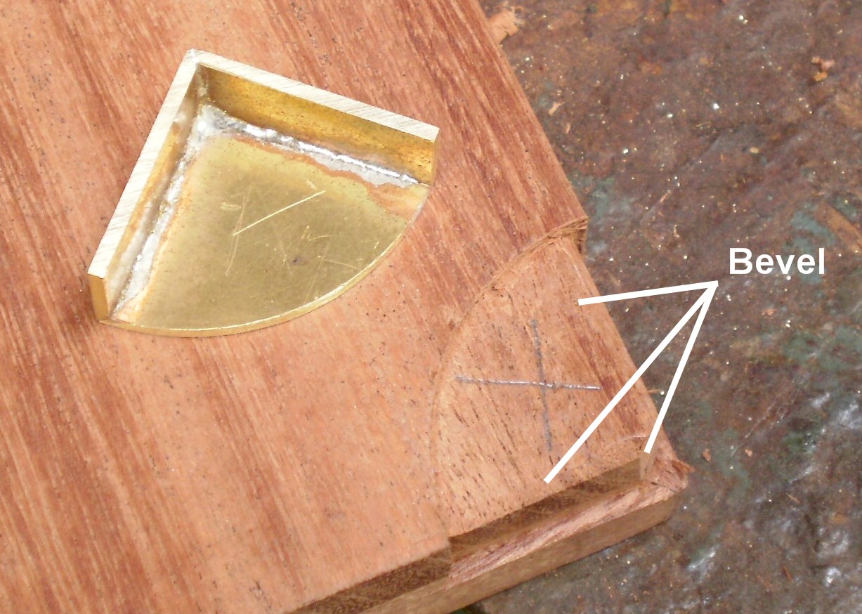
Figure 10: Corner ready to be fitted.
Figure 11 shows a completed lid. Fitting of the hinges is routine, but getting them so that the lid sits squarely is not. The rebates in the lid for the hinges can be marked out from the rebates on the glazed top and new hinges fitted to the lid. It is as well to plug any holes in the glazed top with hardwood pegs if they are likely to be anywhere that new screws are going to go. If you then roll out a thin layer of Plasticine and cut slices to place where the new hinges will go, position the lid correctly and press, the screw holes will be marked out on the Plasticine. You can then drill pilot holes through the Plasticine into the wood in the correct places and get the lid to fit correctly first time. All is not lost if the lid ends up askew. Simply drill out the screw holes in the glazed top to about 5mm and fill the holes with epoxy putty. When dry, it can be drilled for pilot holes without any danger of the screw following the grain of the wood. If you reserve the last coat of varnish until the corners are fitted, you can give the corners a coat that will keep them shiny for a good few years.

Figure 11: Finished lid in place.
The Mariner’s Chronometer is for sale through www.amazon.com and its European equivalents such as www.amazon.co.uk and www.amazon.co.fr ;and this is probably the cheapest way to buy it. I have been greatly encouraged by the reviews left by buyers. I have been making minor modifications to the book as I find better illustrations, especially in the historical section. If you have even a passing interest in marine chronometers, I think you will find the book is well worth buying.

Thanks for finally writing about >8. Making a replacement lid
for the case. | The Mariner’s Chronometer <Liked it!