28: A tale of woe that ended well.

24 11 2017

Apart from Soviet era MX6 chronometers other chronometers are out of my financial reach, unless I buy damaged ones “for parts or repair”. As I now have several MX6 s I can only justify buying another if I challenge myself to right the wrongs it may have suffered. At the beginning of October I returned from the USA with a homeless MX6, of which the seller had said it would not wind beyond 48 hours, whereas 56 hours is the norm. The Department of Homeland Security had rummaged through my baggage, presumably upon seeing with X-rays a dense circular object  with clockwork, and had replaced the layers of bubble wrap after a fashion, so further damage had not occurred.

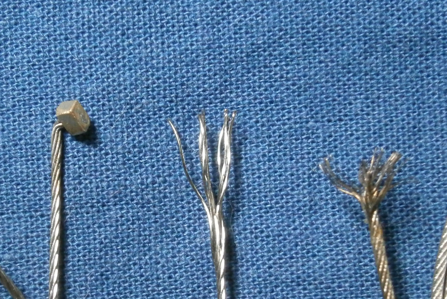
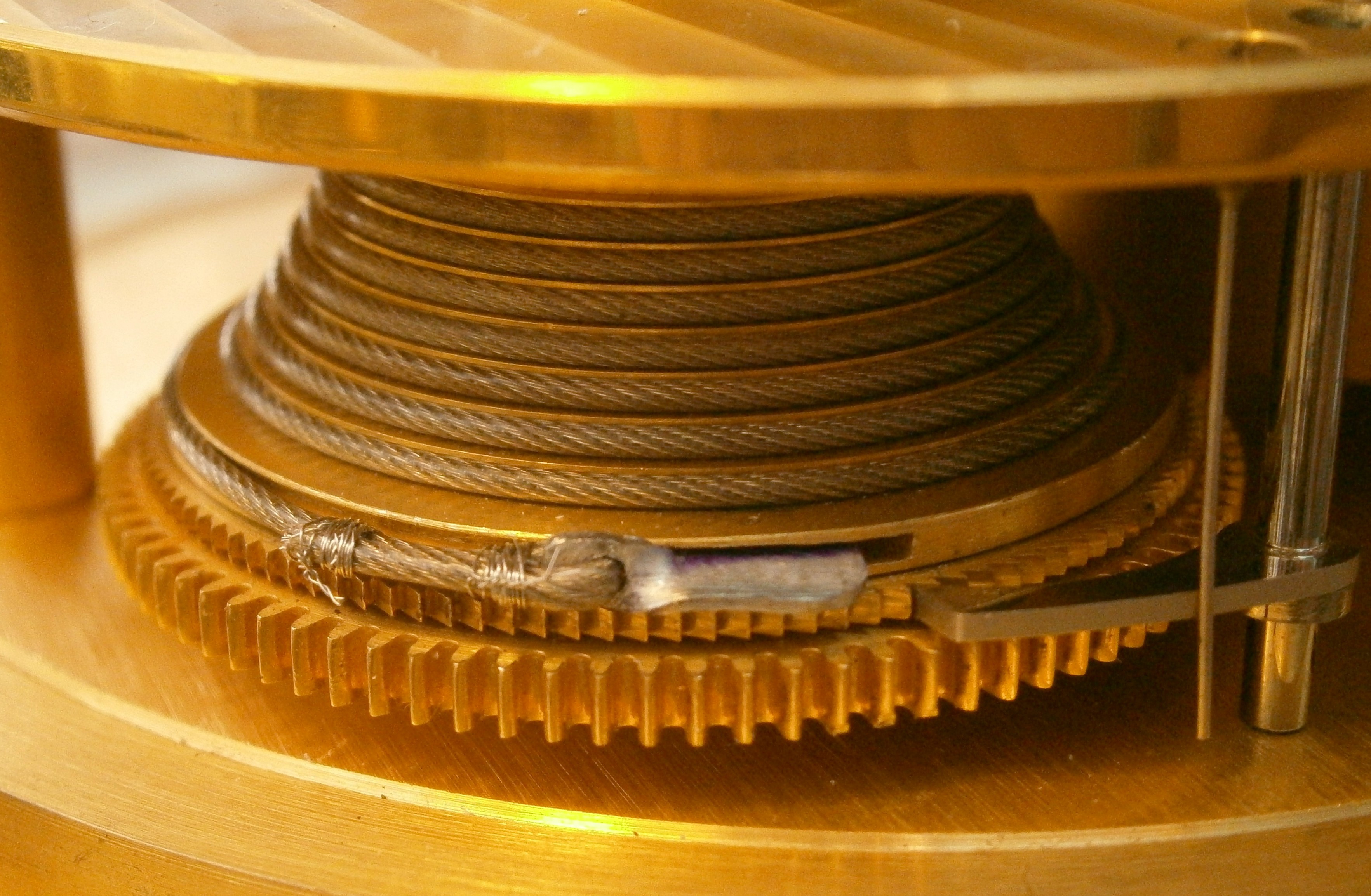
Once recovered from a 15 hour flight from Houston to New Zealand, followed by a 5 hours drive to my home in the Far North, I set about exploring the innards of the instrument. The end of the chain around the barrel was at the back and  the clock ran when started, so, rather incautiously, I wound the clock to 48 hours and continued, forgetting that the stop-work needs a full wind to operate. There came a loud snapping noise followed by a frenzied whirring…Upon opening the machine I of course found that the barrel end of the chain was no longer attached to the barrel, but of a hook there was no sign (Figure 1 – click on the photo to enlarge and use back arrow to return to text)). The barrel arbor had cast off its ratchet, so happily the whirring had come from the barrel rather than from the movement.

Broken chain labelled

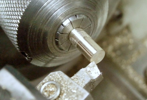
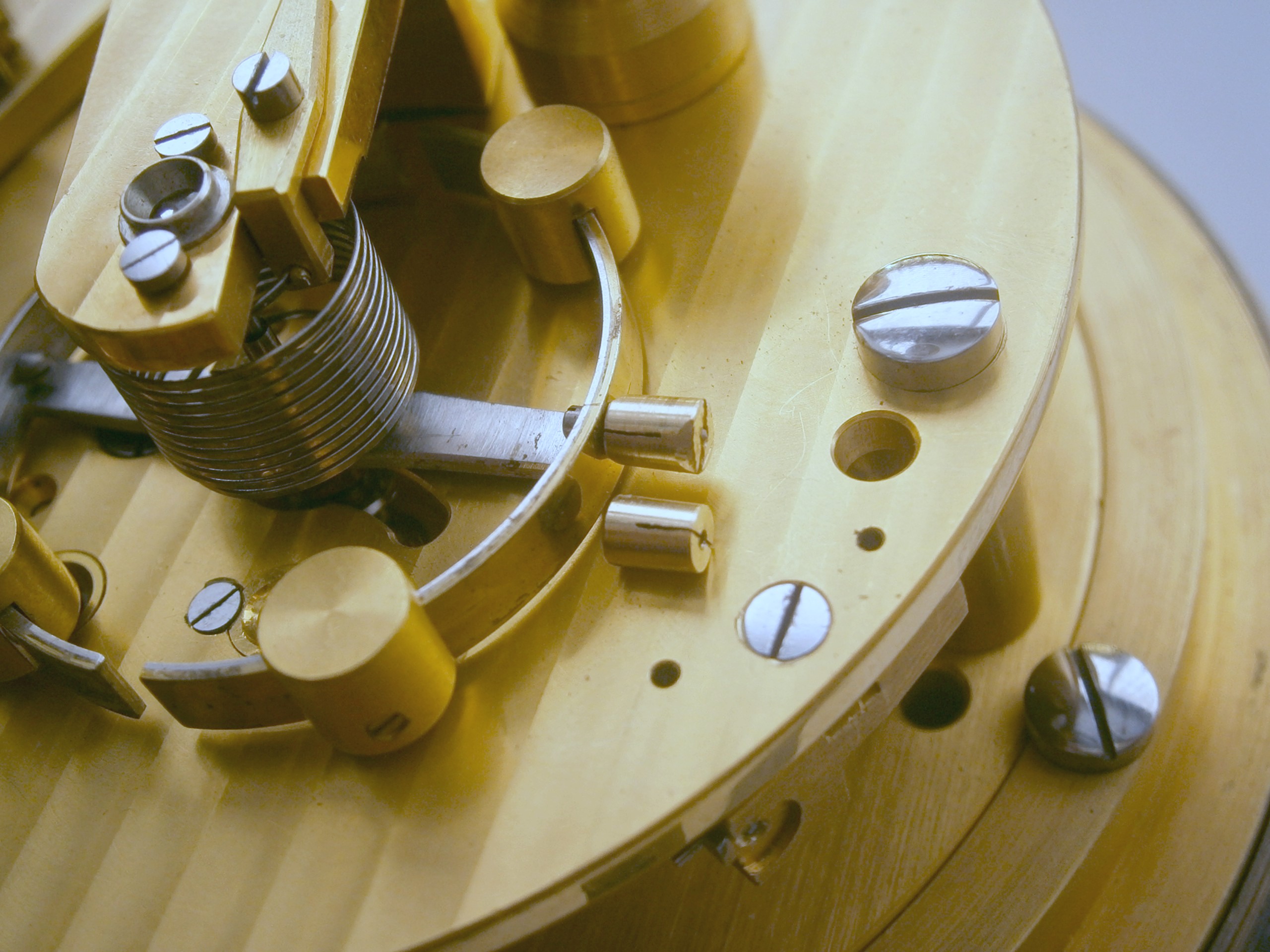
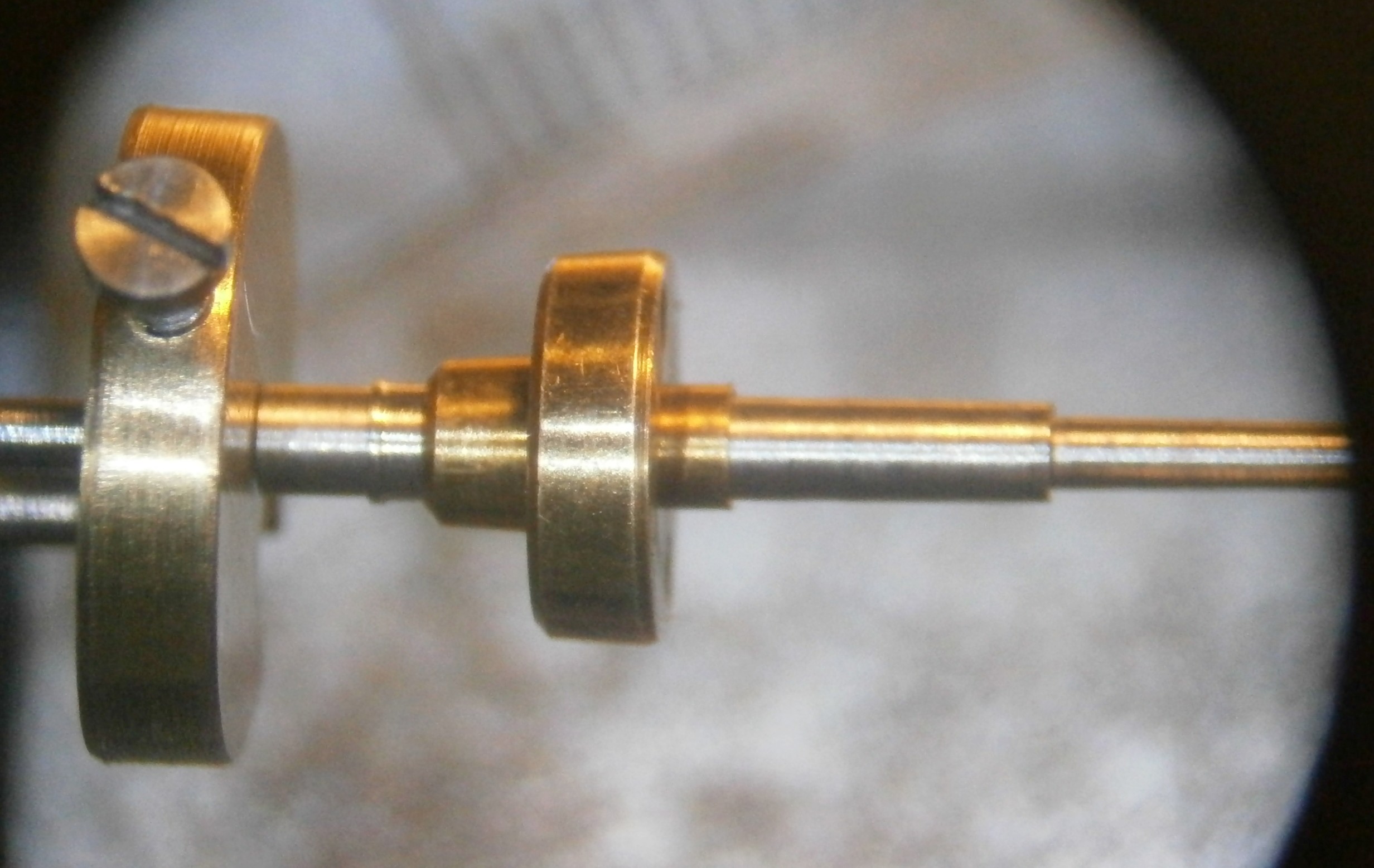
Figure 1: Broken and short chain.

Note how the chain, even if it had had a hook, is still one turn of the fusee short of reaching the stop bar. It seems that someone, not necessarily the seller, had simply stuffed the broken end of the chain  into the barrel slot. In any event, when the chain lost contact with the barrel, either the free end or the recoil of the movement had done a lot of damage. The moral of the story is that you should not wind an obviously defective chronometer to see whether it goes. It should have been obvious to me that a bit of the chain was missing and that the stop work would not operate, risking breakage of the chain at the end of winding if it had a hook into the barrel or, as I found out, the chain simply let go of the barrel. The chain was about 120 mm short of the required length of 850 mm and I replaced it with steel cable as described in post number 27 of 13th February, 2017.

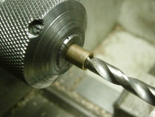
Once fully dismantled, I found that the upper pivot of the escape wheel had been repaired by the classical method of drilling down the broken end and letting in a new pivot. The new pivot was rather short and it had not needed much to knock it out of place. I had a spare escape wheel arbor and pinion which had a broken upper pivot and I used my preferred method of repair, by using a muff, as described in post number 7 of 22nd July, 2013. Using the classical method, if the tiny drill, around 0.6 mm in diameter, breaks off in the broken arbor, you may not be able to get the broken stub out of the hole and, it being made of high speed steel, you won’t be able to drill it out.

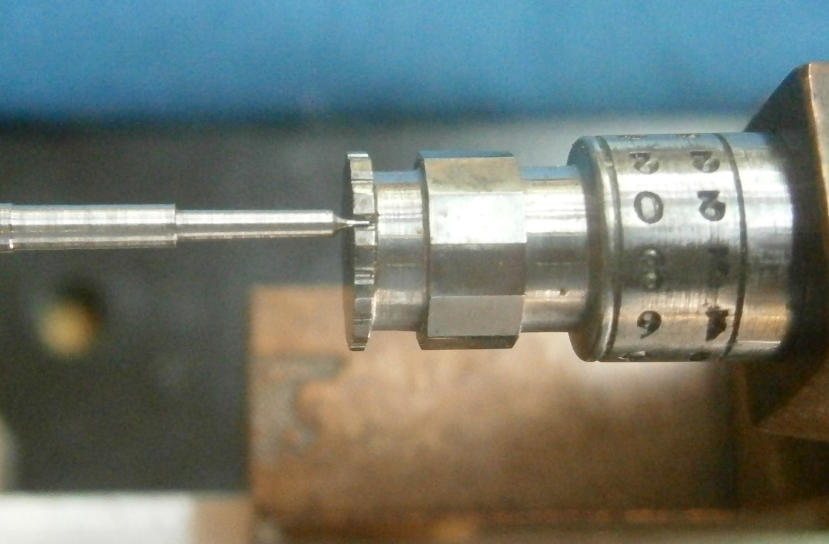
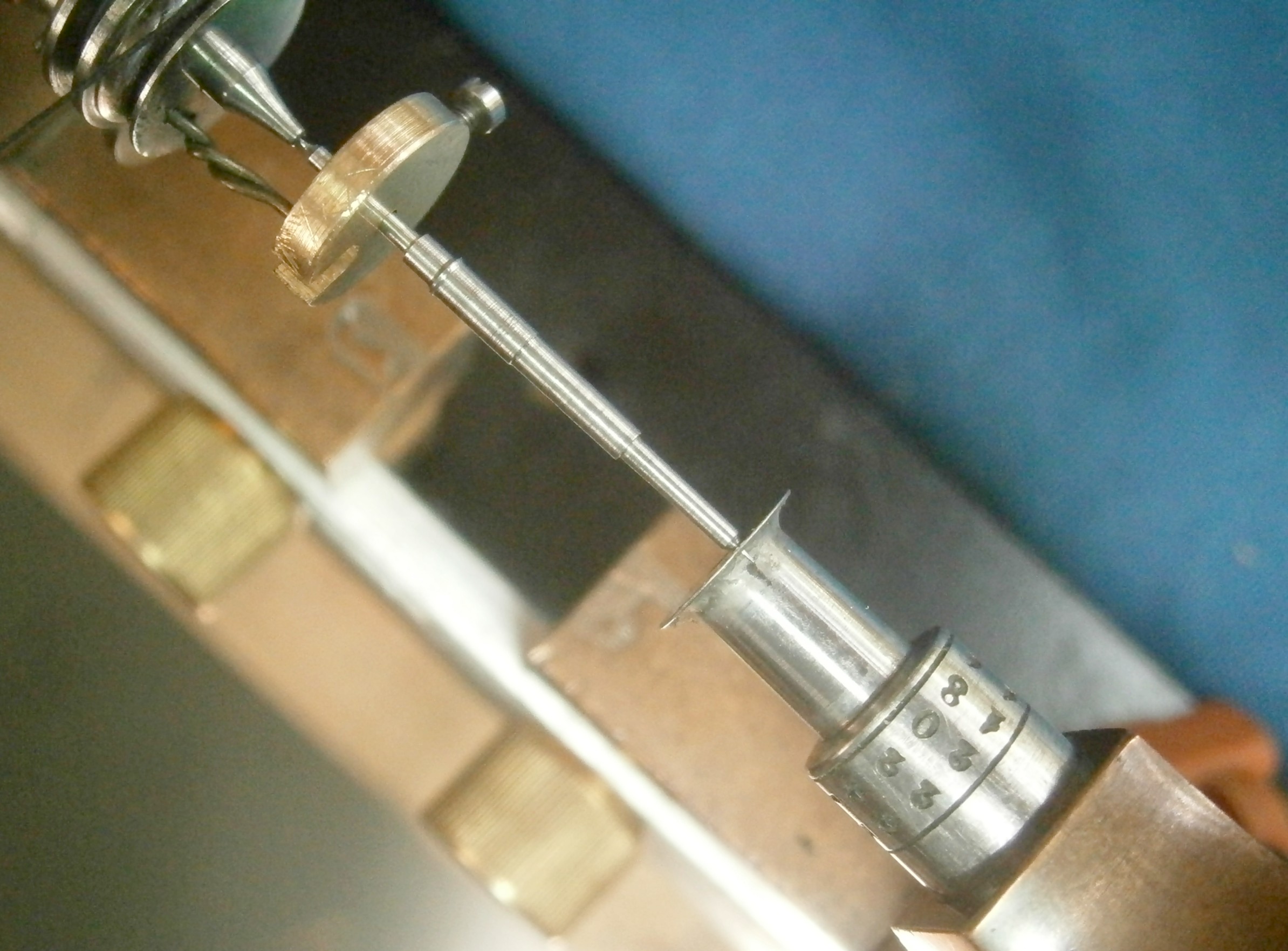
That was the easy bit. The detent spring, which must have been intact when I first tried it, because the clock ran, had taken on a Z-shape. At least it was not broken, and the fact that it had distorted without breaking gave me some hope that I might be able to straighten it. While is was possible to straighten a passing spring by drawing it between my finger nails (see post 22 0f 20th June 2016), the detent spring is made of sterner stuff and so I used a pair of pliers with circular jaws, bending the spring while drawing it between the jaws, as shown in Figure 1, which is posed with a slip of brass shim between the jaws.

Straighten spring 001

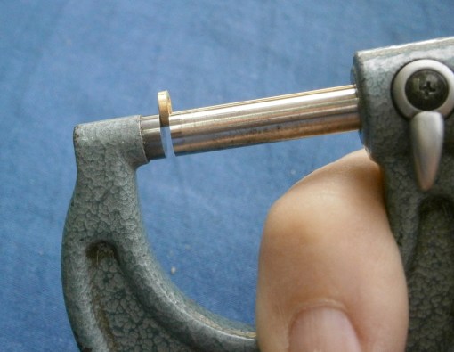
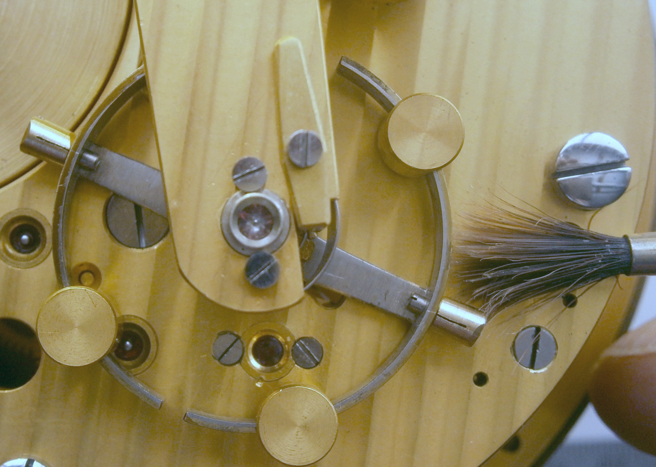
Figure 2: Technique to straighten spring.

Drawing the spring between the jaws, while angling the pliers against the bend, irons out any kink, so that a reverse bend is not simply added to the original bend. Eventually I managed to get the spring straight again without breaking it.

The next step was to replace the passing spring. While some chronometers had oval holes in the passing spring to allow for some adjustment, in the MX6, there is no provision for this and the tip of the passing spring projects rather less than a millimeter beyond the tip of the horn. This means that in adjusting the depth of the detent, this is the total range of available movement and in lifting the passing spring the discharging jewel must pass clear of the tip of the detent. On the return, the jewel must lift the locking stone off a tooth of the escape wheel far enough to unlock the wheel. If the locking stone is too deep in the escape wheel teeth, unlocking won’t happen, so some adjustment of the banking screw (or stop button in the Hamilton M21 escapement) may be necessary. It seems to be about right when a tooth of the escape wheel overlaps about one third of the width of the jewel face.

In making these interdependent adjustments, I start with the locking stone and check that every tooth of the escape wheel is locked by this amount, just in case the upper pivot is bent or for some reason there has been uneven tooth wear. Once I have done this, I then start with the tip of the detent well clear of the discharging jewel and move it in very gradually, operating the escape wheel with a finger until the passing spring is lifted off the horn of the detent. Only then do I check that unlocking takes place on the return stroke. If the depth of the detent is set too deep, the discharging jewel will strike the back of the horn on the return, instead of the passing spring, and refuse to go further because the banking screw stops it, a very good reason for checking the operation of the escapement by hand, rather than under power, which would risk breaking the discharging jewel or a balance wheel pivot.

Then one can wind the chronometer a turn or so and let it run under power, being prepared to stop it at the first sign of tripping, which is usually cured by increasing the depth by a tiny amount each time. This of course assumes that you have not disturbed the mutual angles between the upper balance wheel spring stud, the discharging roller and the impulse roller, another interdependent set of adjustments. I knew that I had all the angles correct and it needed less than an eighth of a turn of the depth-adjusting screw to cure occasional tripping.

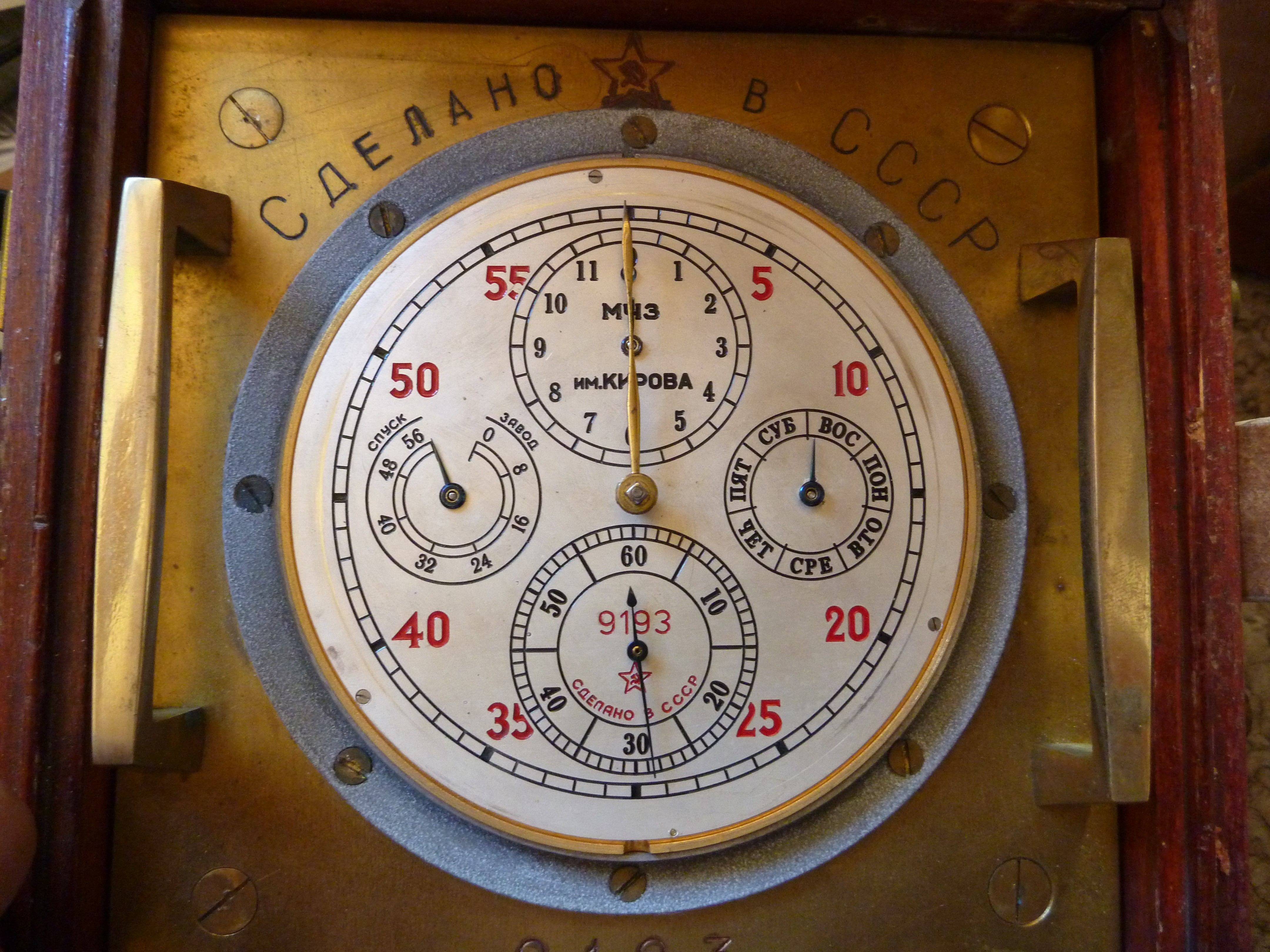
Despite all its trials, the chronometer responded to my ministrations and ran sweetly on a full wind. After some adjustment, it ran over 20 days with a mean gaining error at room temperature of 0.9 seconds per day, with the mean of the deviations from this mean error being 1.03 seconds. Making a case for it took a little while, but it seems happy enough in what I was able to achieve (Figures 3 and 4).

Case 3 4ths view

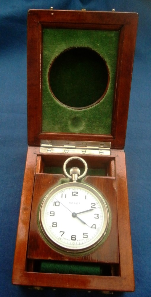
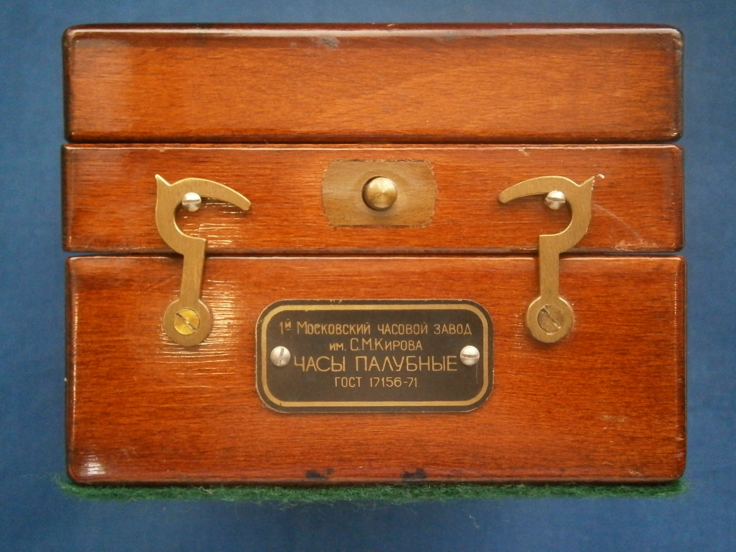
Figure 3: Exterior of new case.

I was able to use some Hamilton handles, but the gimbals lock and the brass corners I had to make myself.

Case open from L

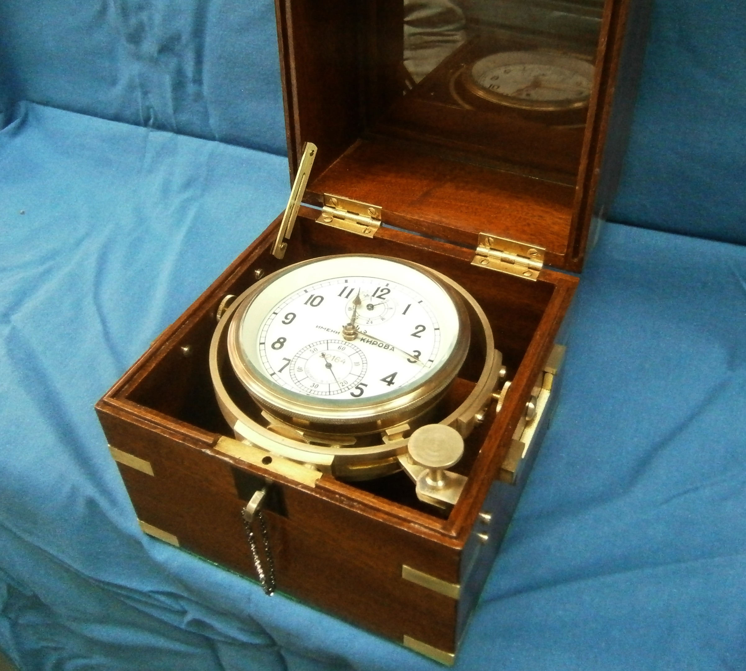
Figure 4: Chronometer in new home.


Advertisement


27: Fusee chain substitute

13 02 2017

A few weeks ago I received a chronometer which seems to have been heavily damaged by dropping, possibly while out of its bowl . The upper balance pivot was broken, the upper jewel of the third wheel was absent, or rather, it was present in many tiny pieces, and there were burrs raised on a few adjacent teeth of the great wheel. The stop bar of the stop work was stuck and the maintaining power did not work. The hands were absent and so was the fusee chain.

I have covered re-pivoting in posts 6 and 7 and making hole stones in post 26, though when there is no end stone to take into account, the process of making one is a rather simple turning operation. A little careful filing removed the burrs on the great wheel. Dismantling the stop work and maintaining power revealed dried-up grease, so that merely cleaning the parts of all old lubricant and replacing it with new brought these back to life. That left the hands to make and the chain to replace. I will cover making hands in a later post.

To a mariner, “cable” used to mean “A large rope by means of which the Ship is secured to the Anchor.” When it became possible in the nineteenth century to make large chains economically, they began to talk of “chain cable”. While the weight lines in clocks were of gut, this presumably was not strong enough to use as the link between spring barrel and fusee, so chain was used. It may well be that the technology of the eighteenth century was not equal to making wire lines that were both flexible and strong, and since chronometer makers were nothing if not conservative, the use of chain continued to the end of chronometer manufacture. These chains, which look rather like miniature cycle chains, were made by specialists and the chronometer repairer limited himself to repairing a broken link, usually by simply removing it.

Such books as there are that tell of chronometer repair are silent on what to do when the chain is completely absent. I found that I could buy a replacement chain for a trifling US$190, but as readers will perhaps by now have gathered, I am no spendthrift, and I began looking for an alternative to chain. The problem resolved itself into several requirements. The replacement has to be strong enough for its task; it has to be flexible enough; and it has to be possible to attach it to the barrel and fusee without special techniques. It also has to fit in the pre-existing groove of the fusee. These groves are always flat-bottomed so that conversion to a round cable is possible.

Less than a kilometre from my house is a famous game fishing club from which tormenters of large fish set sail. It is considered unsporting of the fish to bite through the trace of the hook and so it is often nowadays made of steel wire. A visit to a local supplier of fishing tackle provided me with a metre of stainless steel wire 0.8 mm in diameter for the sum of NZ$1.20 and I thought my problems were at least partly solved.

I carved hooks out of some scrap roofing iron using a piercing saw and files, and immediately encountered some problems: I could not solder the wire to the hooks, it was not flexible enough to allow me to pass it through a hole and bind it back on itself and when I made a little brass bush and squeezed it on to the end of the wire, it projected enough to foul either the top plate or the ratchet wheel of the maintaining power or the centre wheel arbor. By creative bodging I managed to overcome this, only to find that the wire was almost too stiff to be able to fit it. I then recalled that many years ago a kind person had given me a box of bits and pieces that he had bought at a deceased clock maker’s clearance auction with no clear idea what to do with them. Among the bits and pieces were several pieces of flexible wire and one length of the correct diameter to fit between the cheeks of the fusee groove. It appeared to be of multi-stranded steel, was very flexible; and it could be doubled back on itself with relative ease.

A test of its solderability revealed that it was plastic-coated and when I burned off the coating and scraped the wire clean, its fine structure could be revealed and contrasted with the relatively coarse structure of the stainless steel trace wire ( middle, Figure 1). The figure also shows how I at first anchored the trace wire to a hook with a bush.

ends-001

Figure 1: Stainless steel trace (left and centre) and multi-stranded flexible steel (right)

Attaching the cable to the barrel with a normal-shaped hook was relatively easy, using techniques well known to a mariner setting up standing rigging. In my case, after doubling back the wire on itself I held the bight in a small vice while binding it with some fine nichrome wire that I had bought for another purpose. As Figure 2 shows, the free end  just clears the top plate.

attach-to-barrel

Figure 2: Attachment of cable to the barrel hook.

Attaching the other end to the fusee hook required some modification to the normal shape of the hook, as otherwise the standing end of the wire would not lead into the beginning of the fusee groove. Thus, I made the hook deeper than usual so that the end of the hook could be twisted through 90 degrees and bring the cable in line with the fusee groove (Figure 3).

attach-to-fusee-1

Figure 3: Attachment of cable to modified fusee hook.

I have not been able to find a supply of similar wire. Phosphor bronze wire 1.5 mm in diameter is available but is too big. I tried unravelling  a sample of the wire and using only three of the five strands, but it stubbornly refused to be pulled straight. As it was hard drawn, I tried annealing it in a gas flame while pulling on it, but it broke under a very moderate stress. Clock fusee chain is too wide and pocket watch chain is too short.so I am very glad to have been able to find just the right diameter.

After a thorough overhaul and repair, the chronometer sprang into life with a very strong balance motion. I have gradually regulated it  over three days and it is currently losing at the rate of 1.3 seconds a day. I hope that with a little more tweaking it will do a little better.

If any reader knows where to obtain flexible, multi-stranded steel or phosphor-bronze wire of between 0.8 and 1.0 mm in diameter, I would be glad to hear of it.


26: Making a hole stone.

24 01 2017

When chronometers get dropped sometimes it is not only the pivots that suffer. The jewels, often known as “stones,”  sometimes get chipped or cracked. Continuing to run a chronometer with a cracked stone is to invite the pivot to develop grooves and eventually the pivot gives way. A half-dead pivot can be seen at Figure 2 of post number 5 of April 2013. When a stone is chipped and the hole in it becomes irregular, often the chronometer will not run at all, or if it does, may have an irregular rate, or only run one way up. Unfortunately, replacement hole stones in chronometer size are hard to come by for the occasional repairer, though occasionally mounted stones turn up for Soviet chronometers on e-bay – at a price.

Early chronometers had few jewels, but ran well with the pivots running in the brass of the plates, or in bushes let into the plates. A few days ago, I became impatient waiting for a replacement to arrive and thought to make a replacement out of brass. Phosphor-bronze might have been better, but I didn’t have any. The main problem is in drilling the tiny hole required, 0.2mm diameter for the hole stones of the Soviet MX6 chronometer’s balance and escape wheel staffs. It is now possible to buy tungsten carbide drills of this size, but they were intended for drilling fibreglass printed circuit boards using specialised machinery. In the amateur or repairer’s workshop, where the tailstock of the lathe or the drill chuck may not be perfectly co-axial with the lathe axis, drilling a tiny hole off centre results in the drill wobbling and then breaking. In what follows, I have tried to show a method that works for me in producing emergency replacement hole stones, but first, a sketch of an MX6 holes stone. I have not dimensioned it fully, as other makes of chronometers may well need different thicknesses and diameters.

hole-stone

Figure 1: Sketch of MX6 chronometer hole stone.

The upper face of the stone has an annulus  excavated for a depth of about 0.3 mm around a central island and the face of the island is relieved by a “whisker”, perhaps 0.05 mm, so that when the end stone is in place, there is a slight gap between them to allow oil to run by capillary action and form a reservoir. The lower face is also relieved by drilling in stages so as to leave a hole 0.20 mm in diameter and of about the same length. The point of a larger drill leaves a conical lead-in to the hole, to help the end of the pivot to find its way and then an end mill gives a flat-bottomed hole surrounding. it.

5-face-blank

Figure 2: Facing end of the blank.

A scrap piece of brass is first turned down to a close fit in the hole in the plate, in this case 5.00 mm diameter and then carefully faced (Figure 2)

2-excavate-end

Figure 3: Excavating annulus.

Then the annulus is turned away with a round-nosed tool (Figure 3). Note that the tool has negative rake, which gives a very fine finish on brass. It doesn’t matter how deep the excavation is, as long as it is much more than a whisker deep! Then the face of the island is relieved by 0.05 mm, as noted above and the blank parted off  a little over-thick (Figure 4).

3-part-off

Figure 4: Parting off.

One must now digress to make a shallow socket in the end of a scrap of brass bar (Figure 5).

4-make-spcket

Figure 5: Drilling a socket

The diameter of the scrap doesn’t matter as long as it is larger than that of the blank, but the size and the depth of the hole does matter. Unless a drill is perfectly sharpened it is likely to drill over-size, so I suggest making a start with a centre drill, followed in this case by a 4.7 mm drill. Then even a 5 mm drill that has slightly un-equal cutting lips will follow the hole so-formed and be of the correct size. The finish of the walls may not be great, but the size will be right. I made mine a mere 1 mm deep. Before proceeding further, measure the thickness of the blank so as to know how much to take off the thickness. As the faces of parted-off material may slightly concave or convex, measure near the edge, as in Figure 6.

measure-003

Figure 6: Measuring thickness of the blank.

Then the socket is heated gently and annointed with flake shellac to leave an even coating inside. While the shellac is still liquid, the blank is firmly seated in the socket and the whole allowed to cool, when the socket and blank can be replaced in the lathe.

1-face-end

Figure 7: Facing underside of blank.

After careful facing and removing metal to the correct thickness (Figure 7), drilling can begin. Here, careful depth control is essential, using the graduated thimble on the tail stock quill rather than a ruler. A dial gauge could also be pressed into service. Carbide drills are usually sharpened by the four facet method so that they are self-centring, but to make sure, make a dimple with the much more rigid centre drill and then feed in the 1 mm drill carefully to a pre-calculated depth (Figure 8).

6-drill-1-mm

Figure 8: Drilling with 1 mm carbide drill.

In the example shown, this leaves only 0.2 mm for the very slender 0.20 mm drill to tackle and there should be no problem of it wandering off centre , since the larger drill leaves a conical lead in.(Figure 9).

7-drill-0-2-mm

Figure 9: Drilling with 0,20 mm carbide drill.

Although tungsten carbide is a very strong and dense material it is also brittle, so the lathe has to run at high speed and the feed has to be slow to avoid breakages. Once the hole has been drilled successfully, it remains only to use a 3 or 4 mm end mill to form the relieving step. The depth of this must also be calculated, as it is important to leave the conical run-in area to guide the pivot into the 0.20 mm hole. The new stone is now separated from the socket by heating and given a soak in alcohol to remove all traces of shellac, after which the thickness can be checked. It is a good idea to brush the floor around the bench when separating the stone, to make it easier to find it when you drop it on the floor.

Figure 10 is a composite photograph to show both sides.

OLYMPUS DIGITAL CAMERA

Figure 10: The finished stone.

I don’t know how long this improvised lower hole stone for a chronometer escape wheel pivot will last, but at the moment, the instrument is running well and heading for a good rate. I have a French drum clock that was one of  my grandmother’s wedding present in which the relatively fine pivots run directly in the plates and there is no sign of wear at the low power end of the train after over a hundred years of continuous running, so I hope that my stones will also last over a hundred years. If they do not, they are easy to replace.


25:Making a Four Orbit Face and Motion Work.

22 01 2017

With the exception of Figure 1, all figures may be enlarged by clicking on them. Return to the text by using the back arrow.

I have long been aware that the Hamilton Model 21 chronometer had a version with four orbits, that is to say that as well as the usual minute hand it had four subsidiary dials: the usual seconds and power reserve dials with two extra ones to show 24 hours and the days of the week, shown in Figure 1 (I have been unable to trace the source of this photo). The movement of the chronometer is the same as standard, but the motion work, the system of pinions and wheels behind the face that drives the hands, is different. Only 27 were made and were designated Model 221. One sold in 1982 for $6,600, underlining its rarity.

hamilton-21

Figure 1: Hamilton Mod. 21 four orbit face.

When navigating in the vicinity of the International Date Line it is surprisingly easy to take out data from the Nautical Almanac from the wrong day of the week, and on long voyages across the Pacific, when tired, it is also possible to get the Greenwich time wrong by twelve hours. At least, I gather that this was the ostensible reason for making a four orbit version. However, seafarers are a conservative lot and the idea never caught on.

Until recently, I was unaware that the Soviet MX6 chronometer, based on the German war-time Einheitschronometer, had also been made in a four orbit version. However, last October I received an e-mail from someone in Queensland, Australia, together with a photograph of his MX6 4 orbit chronometer (Figure 2).

tony-mantons

Figure 2: MX6 four orbit chronometer face (courtesy of Tony Manton).

The power reserve dial has moved from 12 to 9 o’clock to make room for the hours dial, and a new one has appeared at 3 o’clock for the days of the week. The Australian friend put me in touch with an owner in the USA and while I was waiting for him to respond, a friend in Korea made contact with the Moscow Watch Factory where these chronometers were made to ask whether any of the old workers could shed light on them. It turned out that only a few, experimental ones had been made, but there had been little interest shown in them and no more were produced.

Then Tim Schultz, an owner in the USA was kind enough to send me some photographs of his instrument. Figure 3 shows the face of what appears to be a surveying chronometer with a rubber suspension.  German chronometers with a similar suspension were made during WW II. The words at the top say simply ” Made in the USSR”.

mx6-face-in-box-tim-schultz

Figure 3: Surveying chronometer (Courtesy of Tim Schultz).

Figure 4 shows the motion work, from which it is possible to deduce at least some of the tooth counts of the pinions and wheels.

mx6-motion-work

Figure 4: Motion work of MX6 four orbit chronometer (Tim Schultz)

The power reserve modification is simple enough: the 120 tooth wheel has simply been moved to the 9 o’clock position and remains engaged with the 12 tooth pinion that fits on the end of the fusee arbor. It is not possible to count the pinion teeth beneath the hour wheel, but the reductions between the canon pinion and the hour wheel must of course be two factors of 24. The hour wheel appears to drive a pinion immediately beneath a one-tooth pinion that rotates free on its arbor  and this latter pinion drives the 84 tooth wheel  that carries the days hand. The ratio between the hour wheel and the days wheel must of course be 7 to 1.

At about this time, I acquired a damaged MX6 chronometer for about half of the usual price, and as I was waiting for it to arrive I thought that if I could get it going, I might make it into a four orbit instrument. Accordingly, I mused over possible designs, aided by an aging CAD program to get the approximate placing of wheel and pinions, to see whether my design might work. Figure 5 shows the final result of my musings.

layout

Figure 5: Planned motion work.

The first numbers in the figure are the numbers of teeth in the wheels and pinions and the second number is the Metric module of the teeth.This latter is the diameter in millimetres of the pitch circle of the gear, divided by the number of teeth and is a measure of the tooth size. The pitch circles are shown as dotted lines. The outside diameter is the number of teeth-plus-two divided by the module and is shown as full lines. To avoid having to make a new canon pinion, I kept the old minute wheel too, shown in red at about 2 o’clock, but planned a new pinion for it, so that all the other wheels and pinions could be of 0.3 module rather than the somewhat larger 0.35 module of the canon pinion and minute wheel. This would allow me to fit in all the gears without having to excavate into the foundation ring as in the instrument shown in Figure 4 above. The pinion on the old minute wheel would drive both the new hour wheel and the gear cluster that drives the days wheel. I elected simply to move the power reserve wheel to 9 o’clock. I retained the pivot of the old reserve power wheel for the new hours wheel.

There are various ways to cut the teeth of gears (or more accurately, the space between them). Traditionally, the jobbing clock maker would cut the tooth spaces one by one, using some sort of dividing attachment and the teeth would be of cycloidal form, which can be seen by enlarging Figure 4 by clicking on it. While all the wheels teeth can be cut to correct form with one cutter, the pinions require one cutter for each pinion tooth count up to 8 and in steps of two up to 16 teeth, and these little cutters are astonishingly expensive, with a current unit price of £84, about US$ 104. However, if the teeth are cut by a generating process called hobbing, about which more below, one cutter will cut any number of teeth at a cost of US$ 30, so this is the method that I chose. The tooth form would be involute, which is much more tolerant of errors of spacing of meshing gears. There seems to be a belief among some clock makers that involute gears do not run well when the wheel is driving the pinion, but this is not my experience and the two clocks I have made with involute teeth seem to run exceptionally freely. In any case, in the new motion work the pinions will be driving the wheels.

pinion-hob

Figure 6: Hobbing a 14 tooth pinion.

The hobbing cutter seen in Figure 6 is essentially a screw thread with straight sides and flat top with cutting teeth formed in it. The spindle carrying it is geared to the spindle carrying the gear blank in such a way that for each revolution of the cutter the blank rotates through one tooth space, in the process generating a tooth with curved sides of involute form. The blank is advanced gradually into the cutter until a gear of the required length has been generated. In the figure. a pinion of 12 teeth has just been completed. Figure 7 shows the 84 tooth wheels being hobbed as a batch.

gears-wheel-hob

Figure 7: Hobbing a batch of 84 tooth wheels.

Figure 8 shows a 12 tooth pinion that has been drilled through the centre and is being parted off from the parent metal.

pinion-part

Figure 7: Parting off a pinion.

When it came to removing the pivots of the old motion work and re-positioning the power reserve and minute wheels, I discovered that all the pivots were tapered in form, as were the holes in the wheels and pinions, so that the holes in the plates for the pivots and in the hubs of the gears had to be taper reamed to match the standard taper pins I used for the pivots. Figure 8 shows the new pinion for the old hour wheel being reamed.

pinion-ream

Figure 8: Reaming a pinion.

Once the wheels and pinions had been turned to size, hobbed, drilled and reamed the wheels were ready to have hubs made and fitted. Once this was done I could start to “plant” them. Before this can be done, the correct centre distance has to be determined and transferred to the pillar plate. The traditional tool is called a depthing tool and though I have made my own it is rather easier for the occasional user to make and use the improvised device shown in Figure 9.

planting-2

Figure 9:

Two threaded bushes slide in a slot cut into a substantial slab of brass and can be fixed in place by finger nuts. The holes through the centres of the bushes accommodate round rods, one end of which are machined to a running fit in the gears being fitted and the other end of which carries hardened centre points for locating in a hole or scribing.The central rods can be adjusted in height and locked in position too. The gears are placed on the device and the centre distances adjusted until they run sweetly together, at which point the bushes are locked in place.

punch-mark

Figure 10: Marking for centres.

In Figure 10, in the upper right of the picture, one arc has been scribed from the hole for the days pivot and another from the hole for the centre wheel pivot, though the latter is not clearly visible in the photo. At the intersection a sharp fine prick punch is used to make a shallow mark at the intersection, and its position is checked and coaxed to the exact position if necessary. The shallow mark is deepened and then a 90 degree punch mark made to guide the drill point. In the lower centre of the photo one centre has been set in the hole for the centre wheel arbor and the other has scribed an arc for the new minute wheel. The latter has then been meshed with the hour wheel and an arc scribed, centred on the hour wheel hole. At the intersection of the arcs at lower centre, the hole for the pivot has been punched, drilled and reamed to size.

Once the holes were drilled, it was a simple matter to insert taper pins and tap (not hammer) them into place. Then I turned and drilled the hubs for the wheels  and pinions in brass and fitted them in pairs to check for smooth running. I needed to taper ream the holes in the hub until each gear or gear cluster sat on the pillar plate and ran smoothly on its own before checking that it ran with its partner. I could then mark the taper pins for height, tap them out, cut and smooth off the ends and replace them in their individual holes (there are small manufacturing variations betweeen taper pins). For the days wheel to fit, I had to mill away a couple of millimetres from the diagonal bar that carries the jewels for the third and fourth wheels and I also had to turn a groove in the underside of the days wheel as it otherwise fouled the end of the spring barrel pivot. I could of course have turned off the end of the barrel pivot, but turning the brass of the wheel seemed to be an easier task than removing the tough barrel arbor and grinding off the end. It was also necessary to  reduce some of the hubs in length so that the wheels did not interfere with each other or with the underside of the face.

Figure 11 shows the wheels finally fitted in place, pretty well as I had planned it in Figure 5 This left the face to do.

gears-plan

Figure 11: Plan view of new motion work.

It is important that all the holes are in the right place. The hours, minutes and seconds dials retain their previous centres, so I jig drilled these, the three fixing screws and the tiny hole for the locating pin at about 25 minutes past the hour by clamping the old face to a new disc of 1 mm thick brass and using the old holes as a drill guide for the new.  When planning the positions of the reserve power and days wheels, I used my makeshift depthing tool to set out the distance between the centre and power reserve holes in the pillar plate and used the same setting from the centre wheel to the days wheel. I could then mark out their positions on the brass disc. I also carefully measured this distance and transferred it to the drawing of the face.

Computer aided draughting makes drawing clock faces relatively easy (Figure 12). I printed the design on to high quality paper and rested it face down on a sheet of glass lit brightly from below. That way, I could bring the glue-coated brass back exactly into coincidence by lining up the holes with the hole markings on the other side of the paper. Once the glue had dried, the smaller holes could be opened up by poking through with a tapered scriber and the excess paper around the hole was cut off against the sharp edge of the backing by rotating the scriber. I cut out the large centre hole with a fine-pointed knife blade. A brushing with PVA glue as a size finished the face.

blank-face

Figure 12: Face ready to fit.

With a wide range of fonts available, it was tempting to simply make a copy of the MX6 face, except that the days of the week run anti-clockwise in my design, thereby avoiding some complication. I also felt that copying the MX6 might be construed as forgery, and anyway, I think my face looks more elegant without the red numerals. I did however make a concession to colour when it came to the hands and fitted a red hand for the hours to give it some emphasis. Figure 13 shows the final result, with the hands just loosely in place, as, with all the handling the movement has received, I feel a full overhaul would be wise before putting the chronometer into use. I changed my mind about the red hour hand and there seemed to be little point in retaining a gold-coloured minutes hand so I have blacked it in the final version..

face-corrected-001

Figure 13: Face fitted.

If you have enjoyed reading this post, you will probably enjoy reading my “The Mariner’s Chronometer”, available through http://www.amazon.com and its worldwide branches.

Update 31 January 2017: A more careful tooth count in Figure 4 shows that the canon pinion has 14 teeth and the hour wheel 54 teeth, not 12 and 56 respectively. I have made the appropriate changes to the figure.

Update February 6 2017: Sharp eyed readers will have noticed that in Figure 12, the “Up” and “Down” are incorrectly placed. This has been corrected in Figure 13, which shows the final, final version.

Update February 22 2017: After overhaul daily rate is now + 0.22 seconds per day and mean deviation from the mean over ten days is 0.39 seconds.


.


23: An Improvised Let-down Tool

27 12 2016

A friend from Norway recently asked my advice about a chronometer which had been damaged in transit to him. It seems likely that one or both balance staff pivots have been broken. If so, he will need to access and remove both end stones and hole stones, to remove any bits of the pivots and to check the hole stones for cracks and chips.

The upper stones are easy. He just needs to block the movement and remove the balance cock. However, to access the lower stones, he will have to dismantle the chronometer and to do this the main and maintaining power springs MUST be let down. As someone who pulls apart chronometers and clocks from time to time I have made a proper let down tool that will fit winding squares of various sizes, but it is scarcely worthwhile to make such a tool for one job.

I have viewed a video on the internet which shows a repairer using the chronometer key itself to let down the spring while holding the movement between his knees. He does so successfully, neither bruising his fingers on the key as the spring runs away from him nor dropping the chronometer on the floor. The key can be used with less risk of discomfort and disaster, at the expense of a little woodwork. Figure 1 shows a sketch of a simple key holder. I have not given dimensions, but the octagon is about 40 mm across the flats.

key-holder

Figure 1: Key holder sketch.

Start with a piece of wood about 100 mm long and 40 mm square, and cut a slot about 30 mm deep in it, the same width as that of your key. For the Soviet MX6 chronometer, this is 3 mm, while for most others it is 2 mm.Then drill a hole across the slot. For the MX6, which has a 4 mm hole in it, you can rest the key on a flat and use it as a jig to position the hole for a cross screw. It does not need to be tapped for a screw as a screw passed through the wood and the hole in the key will suffice to keep the key in place. For others, you will need to tap the hole in the wood for a suitable screw to hold the key firmly in place, though if you drill the hole a little larger than tapping size, the screw will usually make its own thread if the wood is fairly soft. This won’t work with hardwoods like mahogany, oak and teak.

Now plane the corners off the square piece of wood  to make a regular octagon. It helps to mark out the octagon, but it does not have to be exact as long as it looks correct. To finish, sand off sharp corners, and stain and varnish the wood. In my stock of stains, I found an old can of stain  labelled “Nordic teak”,  which I thought might be just right for my new Norwegian friend. but when I considered the place of origin of teak, I thought again… Figure 2 shows the finished object with an MX6 key in place.

key-holder-001

Figure 2: Finished let down tool.


21: A Balancing act.

22 04 2016

A little while ago, a friend in South Korea sent me two balances from Soviet MX6 chronometers, to see if I could get them to run to time. One he had found impossible to get slow enough with the available range of adjustment of the timing weights and the other he could not get fast enough.

I first checked the physical dimensions of the balance wheel and its associated rollers and springs and all were very closely similar. The timing weights  were all 4 mm in diameter give or take 0.01 mm and all of the same length. All were 0.40 grams within the limits of precision of my electronic balance, which reads to a precision of 0.01 g (for the record, the whole balance without the spring but with rollers weighs about 12 grams). That left only the elasticity of the springs and as I am not equipped to investigate that , I surmised that in assembling the chronometers, selective assembly may have been used, so that fast springs might have been matched with balances of greater inertia.

I was not about to meddle with the springs, which looked perfectly normal to me, so that left only the timing weights. The fast balance was relatively easy to deal with, by adding weight to the timing weights. My friend had used Blu tack with some success. Tempting as it was to take the quick way out and add a blob of solder to each side and then file it off until each weight was equal, I decided to make a proper job if it by fitting tiny sleeves to the weights. It was a simple matter to turn down a piece of brass bar to a diameter of 5 mm, drill and ream it to 4 mm and part off 3 mm lengths, then cutting  diagonal splits so that it could be sprung in or out if required. As it happened, I was lucky, in that both sleeves weighed exactly the same. To fit closely on the existing timing wights, they had to be sprung in a little, and Figure 1 shows them in place (if you wish, the figures may be enlarged by clicking on them. Return to the text using the back arrow).

Sleeves 001

Figure 1: Close up view of sleeves.

It was then a simple matter to bring the balance to time by fitting it to one of my chronometers and following the procedure outlined in post 13 of this blog. At first, I  timed it every ten minutes, making at first large adjustments and then homing in with ever smaller adjustments over longer intervals, until it was within one second in 12 hours, quite good enough for me and, I hope, for my friend.

The slow balance was more difficult, as it required smaller balance weights. The diameter of the studs on which the weights are screwed is a mere 1 mm, so any new weight I made would need an M 1 thread to be tapped through it and, as it was not possible to predict in advance how much smaller the weight needed to be, I was in for more work that I had realised. I decided to keep the length constant at 4 mm and vary the diameter. I chose 3 mm for a  first attempt. Once a piece of bar had been tuned down to this diameter, it had to be drilled the tapping size for M 1 screws. Getting a 0.8 mm diameter drill to start on centre needs care as, if the drill point starts to wobble, it will not be long before the drill decides to cut off-centre and then break. My solution was to use my smallest centre drill to make a dimple in the end of the bar, just deep enough to start the 0.8 mm drill, and then to back out the drill every milllimetre to clear it of swarf that might cause it to jam and then break.

Once drilled, the piece could then be parted off at 4 mm and chucked to face the other end. Tapping one of these small pieces without breaking the tap requires great care (Figure 2 shows how fragile the tap looks; the ruler is 12.5 mm wide). Usually, brass is turned dry, but an attempt to tap it dry will sooner or later lead to a squeaking noise which, if prolonged will lead to the tap jamming and then breaking, so I have a little pot of extreme pressure oil on my bench to avoid just such a scenario, as taps of this size are very costly. Once a pair of weights have been turned, drilled, parted off, faced and tapped they can be weighed and, if significantly different in weight, a little turned off one face of the heavier weight until both are the same.

Tap

Figure 2: Metric no 1 tap.

The weights then need to be slit longitudinally over most of their length so that the threads can be sprung together to increase the resistance to turning on the studs. If left slack, they will unscrew themselves, eventually fouling  the upper balance cock and bringing the chronometer to a halt. I don’t know how this might be done as a production process using a fine slitting saw. I did it with a piercing saw fitted with the finest blade available. The other end then needs to be slit at right angles to the first cut with a wider saw for a depth of about half a millimeter to form a screw driver slot. The ends of the long slot can be squeezed together with a pair of brass-faced pliers until there is definite resistance to turning the weight by the fingers.

This, my first attempt, weighed in at 0.21 g and was too small, as now the balance could not be got slow enough without the weights fouling the balance cock, so I tried again with a diameter of 3.2 mm, weight 0.24 g. Figure 3 shows one of my first pair alongside the final attempt Now it was so nearly fast enough with the weights screwed fully in that I succumbed to impatience and filed a little off both ends of both weights. My impatience was rewarded and the balance now kept time within 2 seconds a day with the weights screwed out about half a turn.

Cylinders 003

Figure 3: 3.2 mm weight (fitted) with 3 mm weight alongside.

A few words about stopping the balance and adjusting the weights with it in place may save some anguish. If you have a delicate touch, you can stop the balance by using your finger tip, but you may find out that your touch is not quite delicate enough when one or both balance staff pivots break off, so I advise using a small and soft camel hair artist’s brush which I feed in from the side, with it brushing against the timing weights until the balance eventually comes to a safe halt (Figure 4). Note that the brush is at about a right angle to the balance cock as this is where the balance will come to rest (see also Fig 3).

Brush stop

Figure 4: Stopping balance with a brush.

There is no substitute for a delicate touch when it comes to adjusting the weights. If you simply jam a screwdriver into the slots, sooner or later you will break something and it will be painful to your bank balance. Steady the balance with a brush applied to one weight while you deliberately approach the slot in the other with enough magnification to see clearly the slot that your screwdriver tip is aiming for. Provided that your screwdriver tip is in good condition, almost a sharp edge, it needs only to be resting in the slot. You are not driving the weight home. You are coaxing it round. There should be no up or downwards pressure exerted if you value your pivots.

If you ever have to transport a chronometer, it is important to immobilize the balance. Typically, this was done by using tiny wedges of cork underneath the arms of the balance, called “corking the balance, but a little safer to apply is to use six small slips of notepaper folded in two as shown in Figure 5. It is more difficult to break something with paper, and if the top pivot is already broken, the paper will still work to some extent.

stopping-balance-for-transport-001

Figure 5: Blocking balance wheel.


20. A Soviet Deck Watch

13 02 2016

A deck watch was used to carry time from the chronometer or chronometers to the place where sextant observations were being made. Ideally, the chronometer would be kept in a place where the motion of the ship was least, but in most vessels of the 20th century, it was to be found under a transparent window beneath the chart table. Deck watches do not have chronometer escapements, which are liable to be upset by sudden, especially rotatory, movements, but they were usually high class “chronometer grade” watches which could be relied upon to keep a steady rate to within a handful of seconds, not as good as a chronometer, but good enough to transfer the time.

A few months ago, I acquired a Soviet era deck watch. Unfortunately,  the upper balance staff pivot was broken, but I was able to buy a new staff and, for a trifling NZ$100, a local watch maker replaced it for me (I have since acquired the courage to do this myself). He also offered to clean and oil it for another $2 -300, but I declined this, intending to do the work myself. When collecting it, I asked to see his workshop, where he and his apprentice son work and was interested to see that turning on his lathe depended on his skill with a graver. I gave silent thanks that I had been able to obtain a replacement staff, as to have it made from scratch would have been even more expensive.

After a week or two of running, during which I worked at ascertaining its long-term rate of going, it began to stop after about 20 hours, signifying that something was amiss, perhaps a piece of grit jamming a wheel at the low power end of the train or a problem with the driving force. At this point I suspected a problem with the spring or its barrel, but was later to wonder about the stop work. Overhauling the watch gave me an opportunity to illustrate some of its features.

The watch looks like a large, open faced pocket watch with a centre second hand and is contained in a three part wooden outer case (Figure 1). While this particular version is stem wound and set, earlier versions were had a safety setting pin, and the space for this in the case is visible to the left of the stem.

Deck watch 001

Figure 1: Deck watch in case.

The watch is named “Polyet”  (“Flight”) while earlier versions bore the logo of the First Moscow watch factory. On each side of the 6 is found in Russian “Made in the USSR” (Figure 2). The face is protected by a heavy, flat glass and the bezel and watch case itself is made of chromium plated brass.

002 001

Figure 3 shows the placard on the front of the outer case. The first line reads in Russian “First Moscow Watch Factory,” and the second line “Named S M Kirov.” There is a certain irony here, as there is a strong suspicion that Stalin had Kirov murdered in Leningrad in 1934, because of his popularity, and following his death a tractor factory, a military medical academy and other institutions were named in his memory, including, as we have seen, a watch factory. The third line reads “Deck Watch”, while the last line reads GOST, an abbreviation for “State Standard” 17156-71. The outer case is very closely modelled on the outer case of deck watches made by Ulysse Nardin in the 1930s and 40s and, as we will see, so is the movement.

OLYMPUS DIGITAL CAMERA

Figure 3: Front of outer case

The movement is revealed by removing an outer snap off back and an inner dust cover and Figure 4 shows the movement with the major parts labelled. A Ulysse Nardin Deck watch from about 1940 is shown for comparison in Figure 5.  There is a close general similarity, the main differences being that in the Nardin watch the seconds hand, borne on the fourth wheel arbor, is at the more usual six o’clock position and there is a safety setting pin.

Parts labelled

Figure 4: The movement.


Nardin movement

Figure 5: Movement of Nardin deck watch.

Both watches have more than the usual complement of jewels because the balance, the pallets and the escape wheels are all provided with end stones and the train is jewelled to the centre wheel. The extra jewel in the soviet watch is accounted for by the central seconds pinion pivot. The Polyet cocks, plates and wheels are gold plated, with the edges of the cocks carefully  bevelled, with a beautiful Geneva wave finish to the cocks. This latter has no function other than to demonstrate the high quality of the time piece, while remaining hidden from all except the watch maker or repairer.The “1-77” indicates that it was made in the first quarter of 1977. The split, bimetallic balance wheel and the lever escapement are conventional as is the train, except in the region of the seconds wheel. Figure 6 shows the area with the cock removed.

Seconds

Figure 6: Seconds wheel and pinion.

Some watches with centre seconds hands have the jewel for the third wheel pivot mounted in the upper train plate or cock, with a projection through the cock on which the seconds wheel is mounted with a press fit. In this watch, the cock is cut away and the jewel is mounted in a separate cock, which is also jewelled for the pivot of the seconds pinion. The latter is held in its jewel by a delicate little leaf spring which presses against the underside of the pinion. Assembling the cock for the seconds wheel and pinion is difficult to manage without the spring slipping from under the pinion and I found the easiest way was to back off the little screw that holds the spring, to assemble the cock, to manoeuvre the spring into its proper place and then to tighten the screw.

The winding and setting mechanism are conventional but the stop work for the winding is a little unusual for a relatively modern watch in that it uses a Geneva mechanism (Figure 7).

Geneva

Figure 7: Geneva stop-work.

The mechanism is accommodated in a figure 8-shaped depression in the lid of the spring barrel. A square on the spring arbor carries a disc with a tongue and the disc is cut away a little each side of the tongue. Another disc having six arms is mounted and rotates about a shouldered screw. Five out of the six arms have concave ends, but the sixth has a convex end. As the spring is wound, the tongue causes the Geneva to rotate up to five times, with the concavity on the end of each arm allowing clearance for it to do so.However, when it reaches the sixth arm, there is no clearance and winding is brought to a halt.

While it might be thought that the purpose of this stop work was to prevent “over winding”, most people with even a slight knowledge of watch and clock mechanisms will know that it is not possible to over wind, though it is of course possible by brute force to break parts of the winding mechanism. Rather, the purpose of the stop work is to prevent the last part of the spring in contact with the spring barrel from coming in to play, as its power is different from that of the rest of the spring and the power delivered to the escapement and balance wheel would vary too much for good time keeping, Of course, the balance spring is adjusted to be isochronous as far as possible, that is to say that its period of swing is the same whatever the amplitude of the spring, but nothing is perfect…

When I got to the spring barrel, I found that the square had partly disintegrated, perhaps because it had been left dead hard and cracked from a sharp corner or because of the application of brute force (not by me!). At any rate, I was obliged to graft in a new square, and after a thorough clean and oiling of the movement, it has since performed as it should.

I hope you have enjoyed reading about this brief exploration of a fine navigational time piece. If so, I am sure you will enjoy “The Mariner’s Chronometer”, obtainable through amazon.com and its associated world-wide branches.


19. Making an upper balance cock.

8 02 2016

Tim White, from down under in London, very kindly agreed to provide a “Guest Post” about his making a chronometer balance cock. I have added some notes in blue. He is in the process of copying a Hamilton M21 chronometer, using some of the original dimensioned drawings.  Most chronometer upper balance cocks are in the form of a Z (Figure 1). Traditionally, the folds were made by cutting a 92 degree groove in the metal almost the whole way through, bending to 90 degrees and running solder into the groove (See Post 8, Figure 7), but manufacturers later probably used extrusions that were then finished to size and contour.

Fig 3.12.jpg

Figure 1: Common form of balance cock (from The Mariner’s Chronometer).

However,  the chronometer example supplied to the Hamilton Watch Co. in about 1940, for them to assess, was by Ulysse Nardin (Figure 2), who milled it from a solid block and attached it near the edge of the upper plate, so Hamiltons did too (Figure 3). The Nardin method seems to be somewhat over-thought, needing many operations and several settings to complete.

s-l1600 (1)

Figure 2: Ulysse Nardin balance cock.

Internal curves

Figure 3: Underside of Hamilton Watch Co. balance cock

Tim began with a piece of 1½ inch (38 mm) square brass bar which he faced slightly over length in order to mark out and drill 6.5 mm for the 1/8 inch cock retaining screw and counter-boring for the screw head. The hole and counter-bore for the upper balance pivot and its jewel must be accurately located relative to this hole. All other dimensions are “air fits”, that is to say that they do not need as precise positioning and dimensioning, since they are not in contact with other parts. Note that the curves marked with green lines in Figure 3 are not necessary for the part to function and could have been omitted as an economy measure.

Tim continues:

Put in the small 4 jaw and face down to within .005” (0.13 mm),  removing to measure. Remove using 2 jaws only. Clean and replace.

Tighten lightly, then applying tailstock barrel and apply strongish pressure, re-tighten 2 jaws quite strongly. Remove barrel and face .001” at a time measuring after each cut and clean between cuts. Take three final cuts stopping the lathe between cuts. (A depth micrometer, measuring against the face of the chuck, is handy for getting the correct thickness without having to remove the workpiece from the chuck. I use a lump of copper to tap the first face into contact with the face of the chuck.)

Next, I coated one side of block with marking blue and traced the outline of the original cock. It’s difficult to draw the cock from the plans as they are not completely dimensioned, as well as having centres that lie outside the block. In order to cut the 3 curves I made 3 discs of the right diameters attached to a mandrel. Referring to Figure 4, which is modified from the original Hamilton drawing, for curve A, I mounted the block in the machine vice of the vertical slide in the lathe and then aligned the edge of the disk with the scribed outline of the outside diameter. I replaced the disc with a fly cutter with an adjustable cutter and adjusted the tip of the cutter using a calliper until it had the correct diameter. I then cut the curve.

Copy of BALANCE COCK P5labelled

Figure 4 : Outline curves (Hamilton Watch Co., modified)

Next I machined the straight part B, Fig 4.  I then machined the curve C , Fig. 4, mounting the block on the 3.4in (86.36 mm) disc so that the curve marking is exactly lined up with the edge of the disk placing it by carefully marking, drilling and tapping holes so that it can be screwed to the disk. NB I made a counter weight which was weighed and machined until it was the same weight as the block. I then screwed it to the other side of the disc opposite the block and machined it at around 600 rpm (Figure 5 ).

BALANCE COCK 2

Figure 5: Set up for machining curve C

To machine curve D, Fig. 4,  I used the Sherline rotary table. The block could not be rotated by the lathe because the flat straight AB would hit the cutter. I attached the table to the vertical slide with the operating handle protruding towards me. I used the 2.8 in. (71.12 mm) disc (2 x 1.4 in) centred on the table using the table centre arbor and a spacer to plug into the disk. I secured the disk to the table using two sockets in the T slots. I then secured the block to the disk holding it with a small clamp while aligning the curve with the edge of the disk. I then centre popped through the two holes in the block using hardened centres of the correct diameter (transfer punches). I then drilled and tapped the holes and screwed the block to the disk.  Using a 7mm high helix end mill I then machined the short curve manually using small cuts of around .003in (0.08 mm) watching to ensure the mill never got near the flat area. This worked very well. The finish on all surfaces was good enough so that I could sand with 400 wet/dry and finish with 2000 followed by a Simichrome polish.

To machine the inside cuts I attached a round steel plate to the rotary table. In the middle of the disk (bored .4375” – 11.11 mm) I inserted a threaded pin screwed into the table centre. It has a protrusion which is the same diameter as the jewel hole. It protrudes only about 0.075in (1.90 mm) and is used to locate the jewel hole end during machining (Figure 6).

Central pin

Figure 6: Locating pin for jewel hole, and face plate.

The other end is secured by an M3 screw secured into the disk. The table is attached to the vertical slide. The cock is centred using a pin, which has a reduced diameter end .188in (4.77 mm) diameter. Its OD is 3/8 in (9.53 mm) and is held in the headstock spindle using a 3/8in collet. The vertical slide and cross slides are adjusted until the end of the pin goes into the jewel hole. The cross and vertical slides are then locked. Machining is carried out with a milling cutter held in the lathe spindle and the cut is put on by advancing the lathe saddle. I used a dial indicator to monitor cutting depth. I started the cutting at the jewel hole end and progressed outwards. This method worked very well with the M3 screw and centre pin securing the work piece. Figure 7 shows the workpiece secured to the rotary table, ready to be mounted on the vertical slide of the lathe. Originally, the part would have been machined on a vertical milling machine.

Rotary table 001

Figure 7: Work piece mounted on rotary table.

The curve E, Figure 4, is formed by making a filing button set-up using an OD of .400in (10.16 mm) and an ID of .188in (4.77 mm) to fit the hole. These hardened buttons, one each side of the part, were classically called “cheaters”. When the part is to size and shape, the file skids of the buttons.  I ground off any excess then filed the remainder using fine small files. Then I used 2000 grade wet and dry and polished the work with Simichrome.

Figure 8 shows the part after machining, with Figure 9 showing the finished part alongside a Hamilton Watch Co, original. The latter was made of nickel silver, similar to 60-40 brass with about 20 percent of the zinc substituted by nickel, to give a hard, corrosion resistant, white metal. Holes remain to be drilled for securing the balance spring, the upper balance jewels, and the steady pins which ensure that the cock is correctly located on the top plate.

Finish machined

Figure 8: Part finish machined.

BALANCE COCK  4_1

Figure 9: Hamilton original (left) alongside polished new part.


18. Turning a Chronometer Balance Staff

1 02 2016

Turning the balance staff for a chronometer is very different from turning the same item for a watch. For a start, even for a large pocket watch, the staff is unlikely to exceed 8 or 10 mm in length, whereas my example is over 26 mm long, but not greatly thicker, so one has to be constantly aware that the work piece may flex under cutting loads. Since the late 1700’s, engineers’ lathes have been equipped with compound tool slide rests, a sort of “iron hand” to hold and guide the tool in a linear fashion, but for some reason, watchmakers, even today, often use the techniques of the wood turner, albeit on a greatly reduced scale, holding and guiding the cutting tool (“graver”) by hand. It may be that it was hard to justify the cost of a compound slide rest and most of the watchmaker’s lathes on the second hand market today do not have them. Those that do, attract much greater prices than those without.

I recently made slide rests for my Lorch watchmaker’s lathe since I do not have the years left to acquire the skills with the graver. In any case, I would no more think of using a hand tool at the small scale of the chronometer than I would for turning larger diameters on an engineer’s lathe. To put it another way, I proceeded as the amateur engineer of long-standing that I am, rather than as a craftsman watchmaker.

My first task was to take the dimensions of an intact staff and make a drawing. While having a staff with a broken pivot may seem to place one in difficulties, it is a fair assumption that the pivots on both ends will be the same. If both are broken off, one may have to cut and try in the chronometer for which the staff is destined. To measure the small diameters it is necessary to have a clean and well-adjusted micrometer and technique does matter.

Clean the faces of the anvil and spindle by trapping a piece of clean note paper between them and pulling it free. Then check for zero error. Old codgers in engineering shops used to be proud of their sense of “feel”, but I reckon that Mr Mitutoyo must know a thing or two about micrometers and his firm recommend use of the ratchet or friction device, so turn the spindle slowly until the faces meet and until there is one click. Make a note of any zero error or, better, adjust the barrel to read to zero. If you use exactly the same technique when measuring, the measurements will be consistent to within less than 0.005 mm. If you gaily twirl the spindle so the spindle face hits the anvil hard or you twirl so the ratchet sounds like a soccer rattle, they won’t be.

Measuring lengths is a bit more difficult than diameters, but on the whole, they are less important. A steel rule calibrated in half-millimetres and a hand lens may do. A hand lens equipped with a measuring reticule is better and will give measurements precise to 0.1 mm. Better still is a microscope with a moving stage. These usually have verniers that allow measurements to be made with ease to 0.1 mm. To measure over-all length a micrometer is best and the technique is to hold the instrument with the spindle vertical, to rest one end of the part on the centre of the anvil and, while slowly advancing the spindle, move the other end around, exploring the face of the spindle, as it were, for the moment of contact. When this happens, back off a little, centre both ends and take a final measurement using the ratchet for one gentle click. Figure 1 gives the measurements of a Soviet MX6 balance staff (all figures may be enlarged by clicking on them. Use the back arrow to return to the text). If you already have a bench micrometer able to measure over 25 mm, (Post no.5, Figure 3) you probably will need none of this advice.

Balance staff MX6

Figure 1.

Sharp-eyed (or obsessional) readers will note that the reference length dimension does not equal the sum of all the sub-dimensions. This is because the sub-lengths were measured using a microscope moving stage, while the over all dimension was measured using a micrometer, precise to 0.01 mm. Note too that the seats for the rollers, the balance collet and the spring collet are all tapered. It is difficult to be exact about the amount of taper, as the differences in diameter between the ends of the tapers are so small, but the included angle seems to be around 0.8 to 0.9 degrees.

Pivot wire comes in various sizes, including a nominal 2 mm, which in my samples are 1.96 mm in diameter. It comes ready hardened and tempered to a dark blue colour, which is quite a lot harder than mild steel and which can be made much harder, glass hard if need be, but this is too brittle for our purposes. Since all the tapers on this staff are pretty well the same, the first task is to set over the top slide to turn a taper of 0.85 degrees. There is no hope of doing this by measurement and it must be done by cutting and trying on a piece of scrap material, adjusting the set-over until the difference in diameter at the beginning and end of a 10 mm length is 2(10 x tan 0.43) = 0.15 mm. While you are at it, check that the cutting edge of the tool is bang on centre height and that the tool is really sharp, by taking a facing cut on the piece of scrap and watching to see that there is neither a pip left behind (tool too low) or a pip is bumped off (tool too high). I have a large supply of discarded tungsten carbide engraving cutters that I convert to lathe tools for small work and they can be brought to razor sharpness with a fine diamond lap.

Once these adjustments have been made, turning can begin by cutting off a piece of pivot wire about a millimetre too long and holding it a collet chuck (or simply, collet) prior to facing both ends and measuring the length (Figure 2).

0 Face end

Figure 2: Facing the blank

If it is under-size, you will have to start again with another piece. Otherwise, using the graduation on the top slide thimble as a guide, reduce it to the desired length.

The next step is to turn a pivot on one end. The watchmaker of old would have blended the pivot diameter with the rest of the staff diameter by manipulating a graver to give a graceful curve. I use a tool ground flat on top (i.e. no top rake) and to the form desired on the periphery (Figure 3). Measuring the diameter of the pivot needs some care as there is only half a millimetre or so before the diameter starts to increase. I wear a pair of magnifying spectacles to make sure that only the parallel part of the pivot is being measured by the micrometer, and reduce it to 0.01 to 0.02 mm oversize to allow for loss in the burnishing.

2 Pivot turning

Figure 3: Forming a pivot.

The next part might as well be turning for the discharging roller, by allowing just enough of the work piece to project from the collet chuck. If you have enough magnification you may be able to detect a slight wobble of the end of the pivot at this point. This seems to be because the pivot wire is not perfectly round, combined with tiny errors in the collet. For this reason, I rough turn the part to about 0.1 mm oversize and complete the turning between centres (see below). Figure 4 shows this rough turning completed, with enough of the blank protruding to allow the seat for the impulse roller to be rough turned.

4 Rough discharge

Figure 4: Rough turning the seat for the discharging roller.

Next, the workpiece is reversed in the chuck to turn the other pivot and rough turn the seat for the spring collet. Figure 5 shows the staff with all rough turning completed. An idea of the scale may be had from the 3 mm diameter screw head visible in the bottom left corner.

5 Finished rough turn

Figure 5: Rough turning completed.

Figure 6 shows the set up for turning between centres. This ensures that all diameters are concentric with a line joining the two pivots, and also allows the part to be removed for measurement and put back between centres with an assurance that everything will still be concentric.  A brief explanation, referring to Figure 6, may help the non-turner.

Copy of 6 Finishturn collet

Figure 6: Turning between centres for collet seat.

Beginners may have wondered why the pivots take the form that they do, with an elegant curve rather than just being squared off. This is because the hole through the female centre has an outer, conical portion and an inner parallel portion whose diameter is larger than the diameter of the pivot, so that turning forces are taken on a larger and stouter diameter than the pivot itself (Figure 7). The latter, being only 0.2 mm in diameter would likely break off at the first cut.

Centre

Figure 7: Diagram of piviot (left) in lathe female centre (right)

The live centre rotates with the spindle of the lathe as does the driver, which engages in a slot cut into the side of the dog, a little disc of brass secured to the work piece by a screw. The dead centre remains stationary and must be lubricated. Thus, firmly held between centres, the work piece rotates with the lathe spindle and as the tool is traversed by the top slide it takes a cut. Further cuts may be made in a controlled way by advancing the cross slide with its calibrated screw. The top slide also has a calibrated screw, so that the length as well as the depth of cut may be controlled. In Figure 6, the balance collet is literally hanging about, so its fit may be tried after each cut.

Since the staff is very long relative to its diameters and slender, cuts taken must be very light as otherwise the cutting force will deflect the staff away from the cutting edge of the tool, or even spring the staff out of the centres, with consequent damage to the pivots. The tapers are very slow, so that even a small cut will allow a part to slide a considerable way (relatively speaking) on to the taper. Figure 8 shows the balance collet on its seat. A small tap with a punch will slide it up to the shoulder and seat it firmly on to the staff.

7 Balance collet fit

Figure 8: Balance collet on its taper.

The taper for the spring is dealt with next and after that, the dog is placed on the other end, the staff turned end for end, and the remaining two tapers finished to size. All is not lost nowadays if the seat is made slightly too small as an industrial adhesive such as Loctite 603 may be used to provide a permanent join, provided the gap to be filled is not too large. This cannot apply to the discharge roller of course, as it has to be adjustable, and should not be needed for the spring collet as the tolerance is large.

Now the pivots need to be polished and tradionally this was done using a Jacot tool, though the work can be done in a lathe fitted with a suitable tailstock attachment. All my technical dictionaries are silent on who devised this tool, but it was probably Henri Jacot, (1796 to 1868) who worked in Paris in rue Montmorency from 1833 with his brother Julien. On his death, the business was taken over by his nephew Albert Jacot.

8 Jacot g a

Figure 9: General arrangement of a Jacot tool.

The set up is similar to that used for turning between centres, as shown in Figure 9, except that there is no tail centre. Instead one pivot rests in a groove of such a depth that part of the pivot projects above the walls of the groove (Figure 10), while the other pivot rests in a dead centre, about which the driver rotates. Again, the curved part of the pivot plays a part in locating the staff in the device. The correct depth of groove for a given pivot is stamped in hundreths of a millimetre on the end of the tool. In Figure 10 it is 20/100 mm or o.2 mm

9 Jacot close up

Figure 10: Close up of Jacot tool.

Note that most Jacot tools for sale are not large enough to accept a chronometer balance staff, so in mine I carefully milled a register parallel to the axis of the device in two planes. After cutting it into two pieces I could mount it adjustably on a bar to maintain alignment.

As the staff is rotated towards the operator, a burnisher that rests on top of the pivot is pushed away, smoothing and polishing the metal as well as keeping it in place in its groove (Figure 11). It is commonly stated that the process work-hardens the surface, but I doubt that the pressures attainable are sufficient for this. Polishing also reduces the diameter of the pivot slightly. The burnisher is a piece of dead hard steel in which very shallow transverse grooves have been made by dragging it across a piece of emery paper.

10 Burnisher use

Figure 10: Burnisher in use.

The ends of the pivot are dealt with using a slightly different tool in the tail stock (Figure 11). Instead of grooves, the tool has a thin disc of steel with holes of various diameters to suit the pivot, so that as the staff is rotated, a burnisher can approach the end, to be manipulated in such a way as to slightly round the end. If this is overdone, a burr may be raised and if this happens, it can be simply removed by burnishing a slight chamfer.

11 Burnish end

Figure 11: Jacot tool set up to burnish end of pivot.

Figure 12 shows the finished staff, together with the parts to be mounted on it (the spring is slightly distressed and will need more work on it). It is important not to hammer the rollers into place as this risks splitting them, especially the tiny discharge roller which will probably need adjustment anyway, once it has been tried in the chronometer. If a roller will not slide far enough along its taper by pushing it it into place, it is a simple matter to replace the staff between centres on the lathe and remove a whisker or two with a burnisher or very fine file or oil stone.

13 Parts

Figure 12: Finished staff with parts to be mounted on it.

I hope my attempts will help to illustrate one way how to make a balance staff and that too many experts will not be aghast at my methods. I am always happy to receive kindly worded comments, suggestions and corrections.


17: Replacing an impulse jewel

30 01 2016

Escapement jewels may need to be replaced for a variety of reasons. An inexperienced repairer may try to adjust the position of the detent without first blocking the movement and, as an extra precaution, letting down the main and maintaining power. The result is sometimes that the movement “runs away” and jewels get smashed when the detent is released in a panic, instead of quickly getting a finger on to the fourth wheel. Sometimes a sharp mechanical shock will loosen the jewel, for example, when removing the roller from the balance staff; the jewel is secured in its seat with shellac, which is brittle. Injudicious use of alcohol to clean the parts will soften the shellac, which is soluble in alcohol. Sometimes the jewel will just work loose with handling, as happened to me recently when making a trial fitting to a new balance staff I had made.

Replacement is easy, provided one has steady hands and plenty of vision. A loupe may be enough for some people, but I prefer to use a stereo microscope with X 10 magnification, as the working distance is greater and it is easier to get plenty of light where it is needed. Simple ones are quite cheap on the second-hand market. One will also need a low wattage electric soldering iron and a few flakes of shellac, which may be obtained from specialty decorating stores, or possibly from your friendly local French polisher.

First heat up the iron (the business end is copper!) and with a cotton rag wipe off as much residual solder as you can from the tip of the iron. Then anchor the roller with the tip of the iron. Quite soon, you will see residual shellac start to melt, at which point with a pair of fine tweezers feed in a flake of shellac into the jewel seat. A steady pair of hands and two pairs of tweezers are then needed to set the jewel on its end with the acting face aligned with the radial side of the seat (Figure 1). It useful  to pose the parts on a sheet of thin glass, like a microscope slide. This helps to align them correctly and prevents and plastic on the stage of the microscope from melting.

Impulse jewel 001

Figure 1.

The iron is brought into action again until the shellac melts and begins to run, when, with luck, the jewel can be slid into its seat and the shellac allowed to cool. As Figure 2 shows, the business end of a jewel which is simply being put back into its rightful place should be of the correct size , with its working edge concentric with the circumference of the roller. A replacement jewel may be too long, in which case its height will need to be reduced by rubbing the base on a diamond lap. If too short, it simply has to be manoeuvred into the correct place after softening the shellac with the soldering iron.

Impulse jewel 003

Figure 2

The final step is to check that the working face of the jewel has no specks of shellac or dirt on it. Excess shellac can be chipped away with, say, the point of a hypodermic needle and a brief wipe with a rag moistened in alcohol will remove loose chips from the roller.